
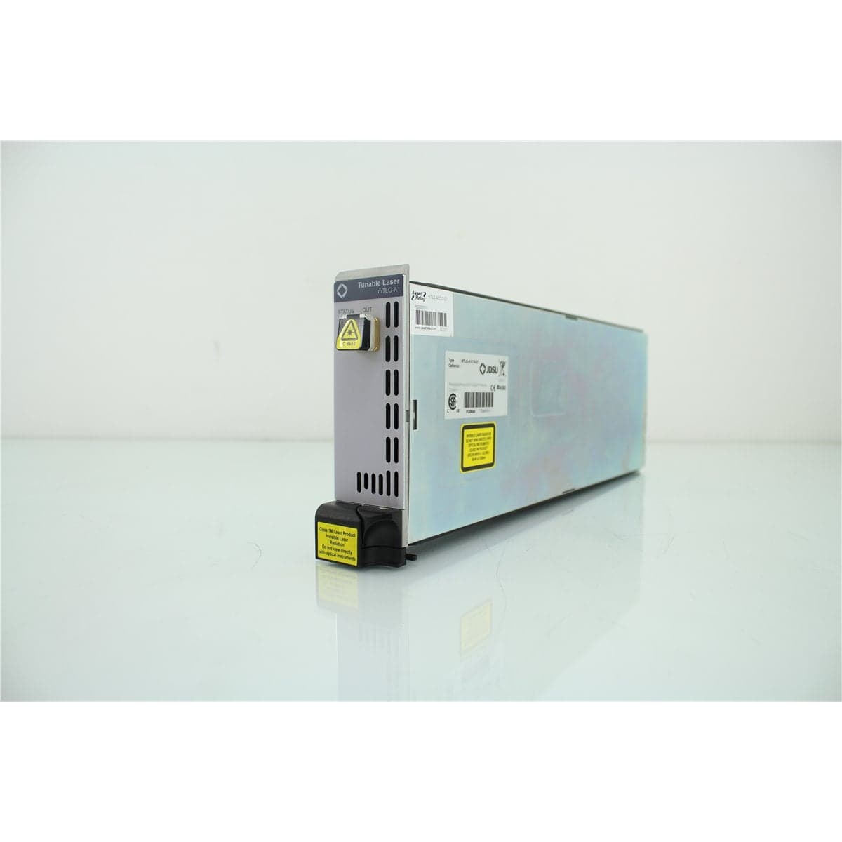
JDS · mTLG-A1C10-27
JDSU mTLG-A1C10-27 C-Band Tunable DBR Single-Laser Module for MAP-200
$3,198.40
Price in USD.
- Condition
- New (open box)
- Availability
- In stock
- Model
- mTLG-A1C10-27
- Manufacturer
- JDS
- Category
- Tunable Laser Sources
Description
JDSU mTLG-A1C10-27 C-Band Tunable DBR Single-Laser Module
The JDSU mTLG-A1C10-27 is a single-channel C-band tunable laser module designed for installation in the JDSU MAP-200 Multiple Application Platform. Based on Sampled Grating Distributed Bragg Reflector laser technology, the module provides precise wavelength selection, controlled optical output power, narrow linewidth, and stable operation for demanding DWDM laboratory and manufacturing applications.
The mTLG-A1C10 configuration contains one tunable laser source. It covers frequencies from 191.30 THz to 196.10 THz, corresponding to wavelengths from 1528.77 nm to 1567.13 nm. Wavelengths can be selected on a 25 GHz channel grid, making the module suitable for testing wavelength-selective components, optical amplifiers, transmitters, receivers, and dense wavelength-division multiplexing systems.
An integrated wavelength locker supports stable wavelength operation, while an automatic power-control loop helps maintain the selected optical output. The module uses polarization-maintaining fiber with the polarization aligned to the slow axis and connector. Its supported optical connector is FC/APC, helping reduce back reflection in compatible single-mode optical test systems.
The mTLG-A1C10-27 requires a compatible MAP-200 chassis for power, local control, display functions, and automated operation. The MAP-200 platform provides a modular foundation for optical laboratory and production testing and supports Ethernet-based LXI connectivity and compatible automation interfaces.
Features and Benefits of the JDSU mTLG-A1C10-27
- Single-channel C-band source: Provides one tunable optical output in a compact MAP-200 plug-in module.
- Wide C-band tuning range: Covers frequencies from 191.30 THz to 196.10 THz and wavelengths from 1528.77 nm to 1567.13 nm.
- 25 GHz channel spacing: Supports fine positioning on a dense optical-frequency grid for DWDM testing.
- Precise wavelength setting: Provides specified wavelength accuracy of ±2 GHz, equivalent to approximately ±0.016 nm.
- Stable wavelength output: Offers typical stability of ±0.005 nm over 15 minutes and ±0.01 nm over 24 hours under the documented conditions.
- Adjustable optical power: Provides a C-band power-setting range from 7 dBm to 13 dBm.
- High maximum output: Delivers more than 12 dBm at the maximum C-band power setting.
- Narrow linewidth: Provides a natural instantaneous linewidth of 5 MHz or less.
- High side-mode suppression: Offers a minimum C-band side-mode suppression ratio of 40 dB and a typical value of 45 dB.
- Integrated wavelength locker: Helps maintain the selected optical wavelength during precision measurements.
- Automatic power control: Stabilizes optical output power during laboratory and production testing.
- Polarization-maintaining output: Uses PM fiber aligned to the slow axis and connector.
- FC/APC optical interface: Supports compatible low-reflection optical connections.
- MAP-200 automation support: Allows wavelength and output power to be controlled through the platform’s local and automation interfaces.
C-Band Wavelength Coverage
The mTLG-A1C10-27 covers the optical C-band from 1528.77 nm to 1567.13 nm. In frequency terms, the module operates from 191.30 THz to 196.10 THz.
This tuning range spans approximately 38 nm and supports many telecommunications wavelengths used in DWDM transmission systems, erbium-doped fiber amplifiers, optical filters, multiplexers, demultiplexers, wavelength-selective switches, receivers, and photonic components.
The module allows the operator to change wavelength on demand without replacing fixed-wavelength sources or manually reconnecting a bank of individual lasers. This simplifies channel-by-channel testing and helps reduce optical setup complexity.
25 GHz Channel Spacing
The JDSU mTLG-A1C10-27 supports wavelength selection on a 25 GHz optical-frequency grid. This fine spacing makes the source suitable for dense wavelength-division multiplexing measurements and other applications requiring close channel placement.
The selected frequency or wavelength can be controlled through the compatible MAP-200 local interface or through supported automation commands. Automated wavelength changes allow the module to be integrated into repeatable component scans, amplifier tests, receiver evaluations, and production procedures.
The wavelength range and 25 GHz grid should be matched to the operating band and channel plan of the device under test. External wavelength verification may be required when a formal measurement record or independent wavelength traceability is needed.
Sampled Grating DBR Laser Technology
The module uses a Sampled Grating Distributed Bragg Reflector laser. This semiconductor architecture provides electronically controlled wavelength selection across the supported C-band range.
The SGDBR design allows one laser module to replace several fixed-wavelength sources in suitable test applications. The operator can select the desired channel through the MAP-200 system rather than physically changing the source.
The source is intended for optical testing and characterization. It should be used within its specified wavelength, power, temperature, humidity, warm-up, connector, and platform requirements.
Integrated Wavelength Locker
An integrated wavelength locker helps maintain the selected output wavelength. This is important in DWDM testing, where relatively small wavelength changes can affect transmission through narrowband filters, multiplexers, demultiplexers, and other wavelength-selective components.
Wavelength stability is specified after a one-hour warm-up, at full power, and with a constant temperature of 25 °C ±3 °C. Under these conditions, typical wavelength stability is ±0.005 nm over 15 minutes and ±0.01 nm over 24 hours.
Actual measurement-system stability also depends on chassis condition, ambient temperature, module warm-up, optical connections, fiber routing, and the stability of the device under test.
Wavelength Accuracy
The documented wavelength accuracy is ±2 GHz, corresponding to approximately ±0.016 nm. This specification supports precise positioning of the source on the selected DWDM channel.
The stated wavelength accuracy applies at full power after the required one-hour warm-up and under the documented constant-temperature conditions.
For applications requiring traceable wavelength verification, the module output can be checked using a compatible calibrated wavelength meter or optical spectrum analyzer with suitable resolution and accuracy.
Adjustable Optical Output Power
The C-band mTLG-A1C10 provides an optical power-setting range from 7 dBm to 13 dBm. Output at the maximum setting is specified at greater than 12 dBm.
Adjustable source power is useful when characterizing components at different input levels, evaluating receiver response, measuring optical amplifier behaviour, and establishing repeatable test conditions.
The optical power setting has typical resolution better than 0.1 dB. A compatible optical power meter should be used when independently verified power at the device under test is required.
Automatic Power Control
The mTLG-A1 includes an automatic power-control loop designed to maintain stable optical output. Typical short-term power stability is specified at ±0.005 dB over 15 minutes, while typical 24-hour stability is ±0.03 dB under the documented conditions.
Stable source power helps reduce uncertainty during insertion-loss, amplifier-gain, receiver-sensitivity, wavelength-response, and component-comparison measurements.
Measured power at the device under test can still vary because of connector loss, fiber movement, polarization conditions, external switches, attenuators, couplers, and patch-cord stability. The complete optical path should be controlled and referenced appropriately.
Narrow Optical Linewidth
The natural instantaneous linewidth of the laser is specified at 5 MHz or less. Narrow linewidth supports optical tests requiring a spectrally controlled source and helps reduce overlap with adjacent wavelength channels.
The source documentation notes that self-homodyne measurements may indicate a typical linewidth from 50 MHz to 100 MHz. This difference reflects the measurement method and should be considered when comparing linewidth values obtained using different instruments or procedures.
The suitability of the source for a specific coherent, interferometric, or high-resolution spectral application should be evaluated using the measurement method and linewidth definition required by that application.
Side-Mode Suppression Ratio
The C-band configuration provides a minimum side-mode suppression ratio of 40 dB and a typical value of 45 dB. SMSR describes the power difference between the selected primary optical mode and the strongest unwanted side mode.
High side-mode suppression helps provide a cleaner optical source for channelized testing, optical amplifier evaluation, receiver measurements, filter testing, and DWDM system characterization.
Spectral verification can be performed with an optical spectrum analyzer capable of resolving the source spectrum and measuring the required dynamic range.
Relative Intensity Noise
The C-band module provides typical relative intensity noise of -140 dB/Hz and a documented maximum of -135 dB/Hz.
RIN describes fluctuations in optical intensity relative to the average output power. Low relative intensity noise supports receiver evaluation, transmission testing, amplifier characterization, and other measurements sensitive to source-amplitude noise.
The measured noise performance of a complete setup can also depend on detector bandwidth, receiver noise, optical reflections, environmental stability, and external components in the signal path.
Polarization-Maintaining Fiber Output
The mTLG-A1C10 uses polarization-maintaining optical fiber. The polarization is aligned to the slow axis and the connector, providing a defined output orientation for compatible polarization-sensitive test systems.
PM fiber is useful when evaluating devices whose transmission, gain, loss, or response depends on the state of polarization. The complete optical path must preserve the intended axis alignment if controlled polarization is required at the device under test.
External patch cords, adapters, switches, and components should be selected for compatibility with the installed PM fiber and FC/APC interface. Mechanical rotation, stress, and mismatched key orientation can affect polarization alignment.
FC/APC Optical Connector
The supported optical connector is FC/APC. The angled physical-contact interface helps reduce optical back reflection when connected to a compatible FC/APC patch cord.
The connector end face should be inspected and cleaned before every connection. Contamination can increase insertion loss, destabilize output power, create unwanted reflections, and damage optical interfaces.
FC/APC and FC/PC connectors should not be directly intermated. Their angled and non-angled ferrule geometries are different and can produce excessive loss or physical damage.
MAP-200 Platform Integration
The mTLG-A1C10-27 is a plug-in tunable laser module for the JDSU MAP-200 Multiple Application Platform. It requires a compatible MAP-200 chassis for electrical power, local operation, module recognition, and automated control.
The MAP-200 is a modular photonic-layer laboratory and manufacturing platform developed for configurable optical test systems. The chassis allows compatible optical modules to be combined according to the required application and available slot capacity.
Wavelength and output power settings can be controlled through the MAP-200 local interface or supported automation interfaces. This allows the tunable laser to operate as part of a larger system containing optical switches, attenuators, power meters, and other compatible modules.
LXI and Automated Test Integration
When installed in a compatible MAP-200 chassis, the mTLG-A1 supports an optical test environment with LAN Extensions for Instrumentation connectivity. The MAP-200 platform is identified as LXI Class C compliant and supports compatible IVI drivers.
Automated control allows test software to set wavelength and power, coordinate the source with other instruments, collect measurements, and execute repeatable production or laboratory procedures.
The exact automation capability depends on the MAP-200 chassis, controller, firmware, software, network configuration, installed modules, and available drivers.
DWDM Transmission Testing
The 25 GHz channel spacing and C-band tuning range make the mTLG-A1C10-27 suitable for DWDM transmission testing. The source can be stepped through supported channels to evaluate wavelength-dependent system performance.
Applications can include testing multiplexers, demultiplexers, optical filters, wavelength blockers, optical switches, transmission fibers, amplifiers, transmitters, receivers, and other channelized components.
A complete DWDM test setup may also require an optical spectrum analyzer, optical power meter, polarization controller, attenuator, switch, bit-error-rate tester, or receiver. These instruments are separate unless specifically included with the module.
Optical Amplifier Testing
The tunable C-band output supports testing of erbium-doped fiber amplifiers and related optical amplifier systems. The source can be set to selected wavelengths and power levels to evaluate amplifier gain, gain flatness, wavelength response, saturation behaviour, and output stability.
Amplifier testing may require additional optical attenuation, power monitoring, optical spectrum analysis, switching, and control equipment. The input and output levels must remain within the safe limits of every component in the test path.
When several wavelengths are required simultaneously, additional source modules or an appropriate multi-channel configuration may be necessary. The mTLG-A1C10 contains one tunable laser channel.
Fiber Characterization
The mTLG-A1C10-27 can be used as a controlled C-band source for characterizing optical fiber and fiber assemblies. Wavelength-dependent loss, transmission response, connector performance, and other supported parameters can be measured by stepping the source across the required wavelength grid.
The source wavelength and output power should be independently monitored when required by the measurement procedure. Reference cables and connectors should remain clean and mechanically stable throughout the scan.
Additional equipment is required for measurements such as chromatic dispersion, polarization-mode dispersion, return loss, or full spectral attenuation.
Transmitter and Receiver Testing
The module can provide a controlled optical stimulus for testing transmitters, receivers, and optical subsystems. Adjustable wavelength and power support receiver-response measurements at multiple C-band channels.
For receiver testing, the optical output can be routed through a compatible programmable attenuator to establish required power levels. Additional modulation equipment may be necessary when the application requires data-bearing or high-speed modulated optical signals.
The module’s tunable source characteristics should be matched to the receiver bandwidth, channel plan, sensitivity, optical power limit, and polarization requirements.
Typical Applications
- DWDM transmission testing
- C-band optical amplifier testing
- Tunable laser grid generation
- Wavelength-selective component characterization
- Optical filter testing
- Multiplexer and demultiplexer evaluation
- Fiber characterization
- Transmitter and receiver testing
- Optical switch and attenuator testing
- Photonics research and development
- Automated optical production testing
- MAP-200 modular test system integration
Product Overview
| Brand | JDSU |
| Model | mTLG-A1C10-27 |
| Product Family | mTLG-A1 MAP Tunable DBR Laser |
| Product Category | C-Band Tunable DBR Laser Module |
| Laser Configuration | Single tunable laser |
| Compatible Platform | JDSU MAP-200 Multiple Application Platform |
| Operating Band | C-Band |
| Supported Connector | FC/APC |
| Fiber Type | Polarization-maintaining fiber aligned to the slow axis and connector |
| Primary Application | Tunable C-band optical source generation for DWDM and component testing |
Wavelength Specifications
| Specification | Details |
| Optical Band | C-Band |
| Frequency Tuning Range | 191.30 THz to 196.10 THz |
| Wavelength Tuning Range | 1528.77 nm to 1567.13 nm |
| Approximate Wavelength Span | 38 nm |
| Channel Spacing | 25 GHz |
| Wavelength Accuracy | ±2 GHz, approximately ±0.016 nm |
| Typical 15-Minute Wavelength Stability | ±0.005 nm |
| Typical 24-Hour Wavelength Stability | ±0.01 nm |
Optical Power Specifications
| Specification | Details |
| Power-Setting Range | 7 dBm to 13 dBm |
| Power at Maximum Setting | Greater than 12 dBm |
| Typical Power-Setting Resolution | Better than 0.1 dB |
| Typical 15-Minute Power Stability | ±0.005 dB |
| Typical 24-Hour Power Stability | ±0.03 dB |
| Power Stabilization | Integrated automatic power-control loop |
Spectral Specifications
| Specification | Details |
| Laser Technology | Sampled Grating Distributed Bragg Reflector laser |
| Natural Instantaneous Linewidth | 5 MHz or less |
| Typical Self-Homodyne Indicated Linewidth | 50 MHz to 100 MHz |
| Minimum Side-Mode Suppression Ratio | 40 dB |
| Typical Side-Mode Suppression Ratio | 45 dB |
| Typical Relative Intensity Noise | -140 dB/Hz |
| Maximum Relative Intensity Noise | -135 dB/Hz |
| Wavelength Stabilization | Integrated wavelength locker |
Optical Interface and General Specifications
| Specification | Details |
| Output Fiber | Polarization-maintaining fiber |
| Polarization Alignment | Aligned to the slow axis and optical connector |
| Supported Optical Connector | FC/APC |
| Required Warm-Up Time | One hour |
| Operating Temperature | 10 °C to 40 °C |
| Operating Humidity | Less than 80% relative humidity from 10 °C to 40 °C, non-condensing |
| Dimensions | 4.06 cm high x 13.26 cm wide x 37.03 cm deep |
| Maximum Weight | Approximately 1.3 kg or 2.95 lb, varying with configuration |
Documented mTLG-A1 Configurations
| Product Code | Description |
| mTLG-A1C10 | C-band single-laser module |
| mTLG-A1C20 | C-band dual-density module |
| mTLG-A1C40 | C-band quad-density module |
| mTLG-A1L10 | L-band single-laser module |
| mTLG-A1L20 | L-band dual-density module |
| mTLG-A1L40 | L-band quad-density module |
| mTLG-A1C1L1 | Combined C-band and L-band dual-density module |
Operating and Measurement Considerations
The mTLG-A1C10-27 should be installed in a compatible MAP-200 chassis before operation. Module insertion, removal, firmware compatibility, slot assignment, and optical safety procedures should follow the requirements of the installed platform.
A one-hour warm-up is required before the documented wavelength and power stability specifications apply. The stability values are specified at full power with the temperature held at 25 °C ±3 °C.
The FC/APC output connector and every connected patch cord should be inspected and cleaned before use. Dust, oil, residue, or damaged end faces can reduce optical power, increase reflection, destabilize measurements, and permanently damage the interface.
The optical output should be routed only to components capable of accepting the configured power. External attenuation may be required before connecting sensitive optical receivers, photodiodes, or low-power measurement instruments.
The output fiber is polarization maintaining. Compatible PM patch cords should use the correct connector-key orientation when controlled polarization is required.
Laser Safety
When installed in a compatible MAP chassis, the mTLG-A1 is identified as meeting Class 1M requirements under IEC 60825-1 A2:2001. Safe operation still requires appropriate handling of optical connectors, fiber ends, and connected equipment.
Users should not look into the optical output, exposed fiber, connector, or collimated beam. Optical instruments, inspection microscopes, and magnifying equipment should be used only with suitable laser-safety procedures.
The source output should be disabled before connectors are inspected, cleaned, connected, or disconnected. Protective caps should remain fitted when optical ports are not in use.
Comprehensive Functional and Performance Testing
The JDSU mTLG-A1C10-27 receives comprehensive functional and performance testing before shipment. Evaluation may include installation in a compatible MAP-200 chassis, module recognition, startup, source enable and disable, wavelength selection, optical power adjustment, FC/APC output condition, and communication through supported platform interfaces.
Optical testing may include verification of tuning across representative C-band channels, output power at selected settings, short-term wavelength stability, short-term power stability, wavelength-locker operation, side-mode suppression, and spectral response when suitable calibrated equipment is available.
The module connector, chassis interface, optical output, faceplate, retaining hardware, labels, and enclosure may be inspected for contamination, damage, excessive wear, or mechanical problems.
The exact testing scope depends on the available MAP-200 chassis, chassis firmware, optical power meter, wavelength meter, optical spectrum analyzer, PM patch cords, FC/APC interfaces, and requested test points.
Calibration Before Shipment
When technically applicable and selected, the JDSU mTLG-A1C10-27 can be calibrated or performance-verified before shipment. Evaluation may include wavelength accuracy, output power, power-setting response, wavelength stability, power stability, and spectral performance at selected C-band channels.
Calibration should use compatible traceable standards such as a calibrated wavelength meter, optical power meter, and optical spectrum analyzer. The MAP-200 chassis, module serial number, firmware, connector type, channel frequencies, wavelength settings, and optical power settings should be identified in the test documentation.
Buyers requiring formal calibration should specify the desired C-band wavelengths or frequencies, optical power levels, number of test channels, connector configuration, certificate type, recorded results, and required measurement uncertainty before purchase.
Buyer Considerations
Buyers should confirm the complete model as JDSU mTLG-A1C10-27. The documented mTLG-A1C10 product code identifies a C-band single-laser module. The additional -27 suffix should be verified from the module label and product configuration records.
The mTLG-A1C10-27 requires a compatible MAP-200 chassis and cannot operate as a standalone tunable laser. Chassis model, firmware, available slots, controller configuration, and automation compatibility should be confirmed before purchase.
The listing should identify whether a MAP-200 chassis, controller, FC/APC patch cord, PM fiber cable, optical attenuator, power meter, network cable, software, drivers, manuals, or calibration records are included.
Only the tunable laser module and accessories specifically identified in the product listing should be considered included.
Why Buy from AssetRelay?
AssetRelay supplies professional equipment and product solutions for fiber optics, telecom, laboratory, production, optical testing, tunable laser applications, photonics, electronic testing, RF/microwave, inspection, and technical research. The JDSU mTLG-A1C10-27 supports telecommunications laboratories, DWDM component manufacturers, optical amplifier developers, production facilities, system integrators, universities, and research organizations requiring a configurable C-band tunable source.
Buyers should review the product photographs, complete model label, MAP-200 compatibility, FC/APC connector condition, PM fiber requirements, wavelength range, output power, firmware compatibility, calibration status, functional test results, and included accessories before purchase.