
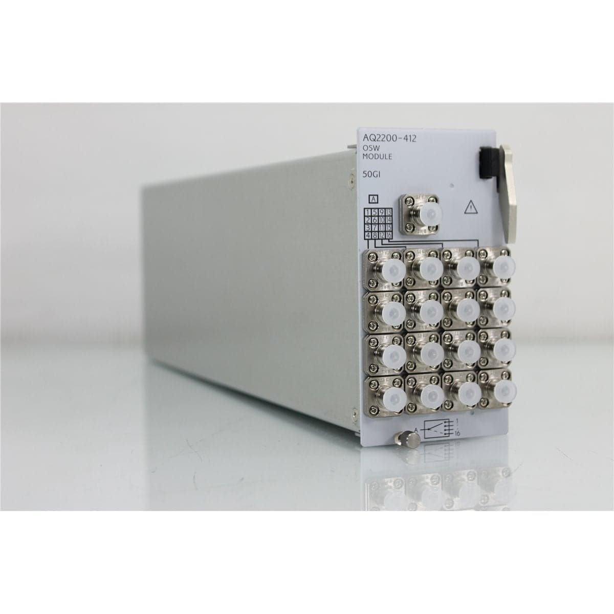
Yokogawa · AQ2200-412-16G5
Yokogawa AQ2200-412 1x16 Multimode 50/125 µm FC/PC Optical Switch Module
$3,192.00
Price in USD.
- Condition
- New (open box)
- Availability
- In stock
- Model
- AQ2200-412-16G5
- Manufacturer
- Yokogawa
- Category
- Optical Switches 50-125 1xN
Description
Yokogawa AQ2200-412 1x16 Multimode 50/125 µm FC/PC Optical Switch Module
The Yokogawa AQ2200-412 is a modular 1x16 optical switch designed for automated routing of optical signals within the AQ2200 Multi Application Test System. This configuration uses 50/125 µm graded-index multimode fiber and FC/PC optical connectors, making it suitable for multimode fiber component testing, optical network equipment evaluation, production verification, and laboratory measurement systems.
The AQ2200-412 routes one optical input to one of sixteen selectable output ports. By replacing repeated manual reconnections with software-controlled switching, the module can improve measurement consistency, reduce connector handling, simplify test sequencing, and support higher-throughput optical test workflows.
The module installs in a compatible Yokogawa AQ2211 or AQ2212 frame controller. These frame controllers provide the power, user interface, remote communication, macro programming, and system-control functions required to operate AQ2200 measurement modules. The hot-swappable AQ2200 architecture allows compatible modules to be installed or removed without switching off the frame controller, supporting flexible system reconfiguration.
Features and Benefits of the Yokogawa AQ2200-412
The Yokogawa AQ2200-412 provides practical value for professional users who require repeatable multimode optical signal routing in automated testing environments.
- 1x16 optical switching: Routes one common optical input to any of sixteen selectable output ports.
- 50/125 µm multimode fiber: This configuration is designed for graded-index 50/125 µm multimode fiber.
- 850 nm and 1310 nm operation: Supports common multimode fiber test wavelengths.
- FC/PC optical connectors: Provides threaded FC/PC interfaces for stable connections in laboratory and production systems.
- Low insertion loss: Provides typical insertion loss of 1 dB, with a specified maximum of 1.4 dB.
- High switching repeatability: Maintains switching repeatability within ±0.01 dB.
- Optical path isolation: Provides crosstalk of at least 50 dB for the multimode configuration.
- Multimode return-loss performance: Provides optical return loss of at least 20 dB.
- Automated test integration: Works with AQ2200 frame programming and remote-control capabilities.
- Hot-swappable design: Supports insertion and removal without powering down a compatible frame controller.
- Modular system configuration: Can be combined with compatible AQ2200 light sources, power meters, attenuators, and other switch modules.
- Reduced connector handling: Minimizes repeated manual disconnection and reconnection during multiport testing.
1x16 Optical Switching
The AQ2200-412 uses a 1x16 topology consisting of one common optical port and sixteen selectable output paths. The module connects the common port to one selected output at a time under control of the AQ2200 frame controller or compatible remote software.
This configuration is useful when a single source, detector, or instrument must be connected sequentially to several optical ports. A test application can select the required path, acquire the measurement, record the result, and continue to the next port without requiring the operator to move a patch cable manually.
The switch does not generate an optical signal or independently measure optical power. A complete test system requires compatible light sources, detectors, power meters, attenuators, or other optical instruments according to the intended application.
50/125 µm Graded-Index Multimode Fiber
This AQ2200-412 configuration is designed for graded-index 50/125 µm multimode optical fiber. The 50 µm value identifies the nominal core diameter, while 125 µm identifies the nominal glass cladding diameter.
The documented operating wavelengths for the multimode switch configuration are 850 nm and 1310 nm. These wavelengths are commonly used when testing multimode fiber links, components, transceivers, couplers, fanout assemblies, and short-reach optical communication systems.
For consistent testing, the source, launch cable, switch module, output cable, detector, and device under test should use compatible multimode fiber. Mixing different core sizes or launch conditions can change modal distribution and affect measured insertion loss.
FC/PC Optical Connections
The module is configured with FC/PC optical connectors. The threaded FC coupling mechanism provides secure mechanical engagement, while the PC-polished ferrule supports physical contact between compatible fiber end faces.
Only compatible FC/PC patch cables and mating interfaces should be used. FC/PC connectors should not be mated directly with incompatible angled-polish connectors because the different end-face geometries can produce excessive loss, unstable readings, and connector damage.
Every connector should be inspected and cleaned before mating. Contamination on an FC/PC end face can introduce additional insertion loss, reduce test repeatability, transfer debris to the module, and potentially damage the connector interface.
Low Insertion Loss
The AQ2200-412 has a documented typical insertion loss of 1 dB and a maximum insertion loss of 1.4 dB. Low switch-path loss helps preserve the available optical power reaching the selected output and device under test.
The measured loss of a complete setup also includes patch cables, adapters, connector interfaces, source launch conditions, detector coupling, and the device under test. The switch contribution should therefore be separated from the total test-path loss through a suitable reference or normalization procedure.
Actual insertion loss can be affected by connector cleanliness, fiber condition, selected port, wavelength, temperature, modal distribution, and the condition of the internal switching mechanism.
Repeatable Automated Measurements
The AQ2200-412 provides switching repeatability within ±0.01 dB. Repeatable path selection is valuable when comparing several ports or repeating the same test sequence over time.
Consistent switching helps reduce variation caused by manually reconnecting patch cables. It can also improve the reliability of production limits, comparative loss measurements, automated reports, and long-duration test sequences.
Overall system repeatability depends on every optical connection in the measurement path. Clean connectors, stable sources, fixed launch conditions, suitable reference procedures, and controlled fiber routing remain important even when an automated switch is used.
Crosstalk and Optical Return Loss
The 50/125 µm multimode AQ2200-412 configuration provides crosstalk of at least 50 dB. Crosstalk indicates the isolation between the selected optical path and unselected paths within the module.
Optical return loss is specified at 20 dB or more for the multimode configuration. Return-loss performance can also be affected by connected patch cables, connector cleanliness, cable movement, device interfaces, unused ports, and the characteristics of the complete optical path.
Unused optical ports should remain covered with suitable dust caps. Port caps help reduce contamination and protect connector surfaces when the module is not connected to a complete test system.
AQ2200 Multi Application Test System Integration
The AQ2200-412 is designed for compatible Yokogawa AQ2200 frame controllers. The three-slot AQ2211 and nine-slot AQ2212 allow optical switches to be combined with other supported measurement modules on one platform.
Compatible module categories include fixed-wavelength light sources, grid tunable laser sources, optical power sensors, optical sensor heads, variable optical attenuators, optical switches, signal generator modules, and optical transceiver interfaces.
This modular architecture allows a user to configure a system around the specific source, routing, attenuation, detection, and control requirements of an application. Module availability and frame compatibility should be verified before installation.
Automated Control and Macro Programming
Compatible AQ2200 frame controllers provide GPIB, Ethernet, and USB interfaces for remote operation. These interfaces allow test software to select switch paths, coordinate light sources and detectors, retrieve measurements, and save results.
The AQ2200 macro programming function supports automated sequences without requiring a computer to remain connected as an active controller. A macro can set module conditions, change optical paths, execute measurements, and save test data.
Up to five users can access a compatible frame controller simultaneously through the supported multi-user function. Remote viewer software can also display and control the frame interface from a connected computer over Ethernet.
Typical Applications
The Yokogawa AQ2200-412 is suitable for professional applications such as:
- Automated 50/125 µm multimode fiber testing
- 850 nm and 1310 nm optical path routing
- Multiport insertion-loss measurements
- Optical transceiver production testing
- Multimode component qualification
- Fiber optic fanout assembly testing
- Optical network equipment evaluation
- Laboratory test-system automation
- Production and quality-control measurements
- Repeated comparison of multiple optical channels
- Research and engineering development
- Service, repair, and diagnostic test systems
Product Overview
| Brand | Yokogawa |
| Model | AQ2200-412 |
| Product Category | Modular Optical Switch |
| Port Configuration | 1x16 |
| Fiber Configuration | Graded-index 50/125 µm multimode fiber |
| Operating Wavelengths | 850 nm and 1310 nm |
| Optical Connector | FC/PC |
| AQ2200 Ordering Code | 735143-16-G5-FCC |
| Compatible Platform | Yokogawa AQ2200 Multi Application Test System |
| Primary Application | Automated routing of multimode optical signals among sixteen test paths |
Optical Specifications
| Specification | Details |
| Port Configuration | 1x16 |
| Number of Switches | One |
| Applicable Optical Fiber | MMF, graded-index 50/125 µm |
| Referenced Fiber Standard | ITU-T G.651.1 |
| Operating Wavelengths | 850 nm and 1310 nm |
| Insertion Loss | 1 dB typical, 1.4 dB maximum |
| Switching Repeatability | Within ±0.01 dB |
| Crosstalk | 50 dB or more |
| Optical Return Loss | 20 dB or more |
| Polarization Dependence | Not specified for the multimode configuration |
| Optical Connector | FC/PC |
Ordering Configuration
| Ordering Element | Code | Description |
| Base Product Number | 735143 | AQ2200-412 Optical Switch Module |
| Port Configuration | -16 | 1x16 optical switch |
| Fiber Type | -G5 | Graded-index 50/125 µm multimode fiber |
| Connector Type | -FCC | FC/PC optical connector |
| Complete Configuration | 735143-16-G5-FCC | 1x16, 50/125 µm multimode, FC/PC configuration |
Compatible Frame Controllers
| Frame Controller | Slot Capacity | Supported Control Interfaces |
| Yokogawa AQ2211 | Three slots | GPIB, Ethernet, and USB |
| Yokogawa AQ2212 | Nine slots | GPIB, Ethernet, and USB |
Automated Multimode Test Applications
The AQ2200-412 can be combined with a compatible optical source and power meter to create an automated multiport loss-measurement system. A source signal can be applied to the common port and routed sequentially to sixteen output paths, or the switch can be used in the reverse direction when supported by the system configuration.
Automated path selection reduces operator interaction and helps preserve stable fiber launch conditions. Test software or a frame-controller macro can coordinate switch selection, power measurement, pass-or-fail comparison, result storage, and transition to the next output port.
The module can also be used for transceiver evaluation, fanout testing, network simulation, multiport device qualification, and repeated routing between a common instrument and several devices under test.
Connection and Measurement Considerations
All test equipment should use compatible 50/125 µm multimode fiber when controlled modal distribution is important. Mixing 50/125 µm and 62.5/125 µm fiber can alter launch conditions and affect measured power or insertion loss.
The connected source should operate at a wavelength supported by the switch configuration. For this multimode version, the documented wavelengths are 850 nm and 1310 nm.
The measurement system should be referenced after the source has stabilized and the required optical paths have been cleaned. A reference measurement can account for the source, launch cable, switch path, output cable, and detector configuration.
Fiber routing should remain stable during precision measurements. Bending or moving multimode patch cables can redistribute optical modes and cause changes in the measured power even when the selected switch path remains unchanged.
Comprehensive Functional and Performance Testing
The Yokogawa AQ2200-412 receives comprehensive functional and performance testing before shipment. Testing may include module recognition in a compatible AQ2200 frame controller, front-panel control, remote path selection, switching through all sixteen output positions, and verification that the selected path corresponds to the commanded port.
Optical testing may include insertion-loss checks, switching repeatability, path continuity, isolation between selected and unselected ports, and return-loss evaluation using suitable multimode test equipment at supported wavelengths.
The FC/PC connectors may be inspected for contamination, damaged threads, loose adapters, scratched ferrules, or other physical conditions that can affect optical performance. Repeated switching can also be used to identify intermittent paths or unstable internal connections.
The exact test wavelengths, launch conditions, optical source, detector, reference procedure, measurement uncertainty, and recorded results depend on the available equipment and the condition of the individual module.
Buyer Considerations
Buyers should confirm the complete configuration as a 1x16 AQ2200-412 with -G5 50/125 µm multimode fiber and -FCC FC/PC connectors. Other AQ2200 optical switch configurations may use single-mode fiber, SC/PC connectors, different port counts, or different supported wavelengths.
The AQ2200-412 requires a compatible AQ2200 frame controller and should not be considered a standalone optical switch. The frame controller, sources, optical power meters, attenuators, patch cables, adapters, software, and accessories may be required separately.
The condition of all seventeen optical interfaces, including the common port and sixteen switched ports, should be reviewed. Connector cleanliness, port labeling, switch recognition, path selection, enclosure condition, and compatibility with the intended frame should be confirmed before purchase.
Only the optical switch module, frame controller, patch cables, connector adapters, dust caps, software, documentation, calibration records, and accessories specifically identified in the product listing should be considered included.
Why Buy from AssetRelay?
AssetRelay supplies professional equipment and product solutions for fiber optic, telecom, laboratory, production, inspection, cleaning, electronic test, RF/microwave, and photonics applications. The Yokogawa AQ2200-412 provides automated multimode optical routing for engineers, laboratories, manufacturing facilities, quality teams, service organizations, and technical procurement groups.
Buyers should review the provided product photographs, physical condition, complete suffix configuration, connector condition, compatible frame requirements, switching operation, optical performance, included accessories, and testing information before purchase.