
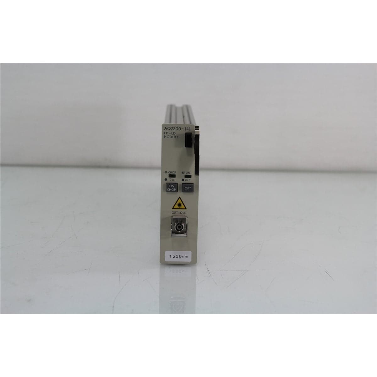
Yokogawa · AQ2200-141-1550
Yokogawa AQ2200-141 1550 nm FP-LD Optical Light Source Module with FC/PC Output
$3,192.00
Price in USD.
- Condition
- New (open box)
- Availability
- In stock
- Model
- AQ2200-141-1550
- Manufacturer
- Yokogawa
- Category
- DFBs
Description
Yokogawa AQ2200-141 1550 nm FP-LD Optical Light Source Module
The Yokogawa AQ2200-141 is a single-wavelength Fabry-Perot laser diode source module designed for installation in a compatible AQ2200 Series Multi Application Test System frame controller. This configuration operates at a nominal wavelength of 1550 nm and uses an AQ9441 FC universal adapter to provide an FC/PC optical interface.
The AQ2200-141 provides at least 0 dBm of optical output through ITU-T G.652 single-mode fiber. Its broadband Fabry-Perot laser output has a documented center wavelength of 1550 nm ±20 nm and a spectral width of 10 nm or less for the 1550 nm configuration.
An integrated optical attenuator provides 6 dB of adjustment in 0.01 dB steps. This allows the output level to be reduced directly through the host frame without requiring an external attenuator for every test configuration.
The module also supports internal modulation at 270 Hz, 1 kHz, and 2 kHz. These modulation frequencies can assist with fiber identification, continuity testing, source recognition, and optical power measurements using compatible receiving equipment.
The AQ2200-141 is a modular source and cannot operate independently. A compatible Yokogawa AQ2201 or AQ2202 frame controller is required to provide operating power, display functions, local controls, module recognition, data storage, and remote communication.
Features and Benefits of the Yokogawa AQ2200-141
- 1550 nm optical source: Provides a nominal 1550 nm signal for compatible single-mode telecommunications and optical component testing.
- Fabry-Perot laser diode: Produces broadband laser output with a documented spectral width of 10 nm or less.
- At least 0 dBm output: Delivers a minimum optical output of 1 mW under the documented operating conditions.
- FC/PC optical interface: Uses an AQ9441 FC universal adapter for connection to compatible FC/PC patch cords.
- Single-mode fiber configuration: Supports ITU-T G.652 single-mode optical fiber.
- Internal optical attenuation: Provides a 6 dB adjustment range for controlled source-level reduction.
- Fine attenuation steps: Allows attenuation to be set in 0.01 dB increments.
- Internal optical modulation: Supports selectable 270 Hz, 1 kHz, and 2 kHz modulation frequencies.
- Stable optical output: Supports repeatable power measurements and comparative optical testing.
- Modular test-system integration: Operates alongside compatible AQ2200 optical sensors, attenuators, and switches.
- Hot-swappable platform: Can be installed or removed within a compatible AQ2200 frame without switching off frame power, subject to proper handling and warm-up requirements.
- Automated test support: The compatible host frame provides Ethernet and GPIB communication for remote operation.
1550 nm Fabry-Perot Laser Source
The AQ2200-141 uses a Fabry-Perot laser diode to provide optical output in the 1550 nm telecommunications region. The documented center wavelength is 1550 nm ±20 nm.
The source is intended for applications where a stable broadband laser signal is suitable, including insertion loss testing, passive component evaluation, received-power measurements, fiber link testing, and laboratory transmission experiments.
The AQ2200-141 should not be described as a narrow-linewidth DFB source. Its documented 1550 nm spectral width is 10 nm or less, making it appropriate for measurements that do not require a single-frequency optical carrier.
Minimum 0 dBm Optical Output
The module provides an optical output level of at least 0 dBm, equivalent to at least 1 mW. This level is suitable for testing compatible passive components, patch cords, couplers, splitters, switches, attenuators, and optical receivers.
Actual power delivered to the device under test depends on the module output setting, internal attenuation, adapter condition, fiber cleanliness, patch-cord loss, and external optical components.
A calibrated optical power meter should be used when the exact power at the device under test must be documented. The optical input limits of connected receivers and detectors should be verified before the source is enabled.
6 dB Internal Optical Attenuator
The AQ2200-141 incorporates an internal optical attenuator with a documented range of 6 dB. Attenuation can be adjusted in 0.01 dB steps through the compatible AQ2200 frame controller.
This function allows the source output to be reduced without disconnecting the fiber path or installing a separate variable optical attenuator. It is useful for comparative measurements, receiver testing, component characterization, and procedures requiring several controlled optical levels.
The attenuation setting represents the module’s internal adjustment. External connectors, patch cords, adapters, switches, and devices can introduce additional optical loss.
270 Hz, 1 kHz, and 2 kHz Internal Modulation
The AQ2200-141 supports internal modulation at 270 Hz, 1 kHz, and 2 kHz. A compatible optical power meter or receiver can detect these frequencies to identify the source and distinguish the test signal from unmodulated optical power.
Modulated operation can assist with fiber continuity testing, link identification, field troubleshooting, source recognition, and optical component measurements.
The selected receiving instrument must support the chosen modulation frequency. Internal modulation should not be confused with high-speed digital data modulation.
FC/PC Optical Output
This AQ2200-141 configuration uses the AQ9441 FC universal adapter, providing an FC/PC optical interface. Compatible FC/PC single-mode patch cords should be used with the source.
FC/APC connectors must not be directly intermated with the FC/PC adapter. The angled and non-angled ferrule geometries are incompatible and can cause high loss, poor optical coupling, unstable readings, or connector damage.
The adapter and mating patch cord should be inspected and cleaned before every connection. Contamination can reduce delivered power, increase reflection, destabilize measurements, and damage both optical end faces.
ITU-T G.652 Single-Mode Fiber
The AQ2200-141 is specified for ITU-T G.652 single-mode fiber. The external optical path should use compatible single-mode patch cords and components when accurate and repeatable measurements are required.
Maintaining the correct fiber type helps preserve the intended launch condition. Multimode patch cords should not be substituted in a precision single-mode measurement system.
Fiber cables should be protected from excessive bending, twisting, pulling, crushing, and repeated movement. Changes in fiber routing can alter optical loss and measurement repeatability.
AQ2200 Series Frame Compatibility
The AQ2200-141 operates in compatible Yokogawa AQ2200 Series frame controllers. The AQ2201 provides three module slots, while the AQ2202 provides nine module slots.
The host frame supplies electrical power and provides a 320 x 240-pixel color TFT display, local controls, measurement applications, data storage, module recognition, and supported Ethernet and GPIB interfaces.
AQ2200 modules are hot-swappable, allowing the system configuration to be changed without shutting down the host frame. The module must still complete the required warm-up period before measurements requiring documented optical stability are performed.
Typical Applications
- 1550 nm single-mode fiber testing
- Optical insertion loss measurement
- Fiber optic component characterization
- Coupler and splitter testing
- Optical switch evaluation
- Patch-cord and connector testing
- Optical attenuator characterization
- Receiver and detector testing
- Modulated source identification
- Fiber transmission experiments
- Automated production testing
- Telecommunications laboratory applications
Product Overview
| Brand | Yokogawa |
| Model | AQ2200-141 |
| Product Category | Fabry-Perot Laser Diode Source Module |
| Source Configuration | Single wavelength |
| Nominal Wavelength | 1550 nm |
| Optical Output | At least 0 dBm, or 1 mW |
| Optical Fiber | ITU-T G.652 single-mode fiber |
| Optical Interface | AQ9441 FC universal adapter with FC/PC connection |
| Compatible Frames | Yokogawa AQ2201 and AQ2202 frame controllers |
| Standalone Operation | Not supported |
| Primary Application | Stable 1550 nm optical stimulus for fiber and component measurements |
Optical Specifications
| Specification | Details |
| Laser Type | Fabry-Perot laser diode |
| Center Wavelength | 1550 nm ±20 nm |
| Spectral Width | 10 nm or less at 1550 nm |
| Optical Output Level | At least 0 dBm |
| Equivalent Minimum Output | 1 mW |
| Optical Attenuation Range | 6 dB |
| Attenuation Setting Step | 0.01 dB |
| Internal Modulation Frequencies | 270 Hz, 1 kHz, and 2 kHz |
| Applicable Optical Fiber | SMF, ITU-T G.652 |
| Optical Connector | FC/PC through the AQ9441 FC universal adapter |
Output Stability
| Stability Interval | Documented Performance |
| Short-Term Stability | Within ±0.003 dB under the documented measurement conditions |
| 24-Hour Stability | Within ±0.03 dB under the documented measurement conditions |
Configuration Identification
| Model or Option | Description |
| AQ2200-141 | Single-wavelength FP-LD source module |
| W1550 | 1550 nm wavelength configuration |
| FCC | AQ9441 FC universal connector adapter |
Related AQ2200 FP-LD Modules
| Model | Configuration |
| AQ2200-141 | Single-wavelength FP-LD source available in 1310 nm or 1550 nm configurations |
| AQ2200-142 | Dual-wavelength 1310 nm and 1550 nm FP-LD source module |
Installation and Operation
The AQ2200-141 should be installed securely in an available slot of a compatible AQ2201 or AQ2202 frame controller. The frame should recognize the module and make its output, attenuation, and modulation functions available through the local interface.
A clean FC/PC single-mode patch cord should be connected to the AQ9441 FC adapter. The required output level and internal attenuation can then be selected through the frame controller.
The optical output should begin at a reduced level when a new device under test is connected. Power can then be increased while the receiving equipment and device limits are monitored.
The module should be allowed to warm up before measurements requiring specified output stability are recorded.
Laser and Connector Safety
The AQ2200-141 emits infrared optical radiation near 1550 nm. This wavelength is invisible to the human eye, and the absence of visible light does not indicate that the source is disabled.
Users should not look into the output adapter, patch cord, connector, or exposed fiber end. The source should be disabled before optical interfaces are inspected, cleaned, attached, or removed.
Only compatible FC/PC interfaces should be connected to the installed AQ9441 FC adapter. FC/APC connectors must not be directly intermated with this configuration.
Comprehensive Functional and Performance Testing
The Yokogawa AQ2200-141 receives comprehensive functional and performance testing before shipment. Evaluation may include installation in a compatible AQ2200 frame, module recognition, startup, output enable and disable operation, internal attenuation control, and modulation at 270 Hz, 1 kHz, and 2 kHz.
Optical testing may include output-power verification at 1550 nm, spectral-width evaluation, short-term stability, 24-hour stability when requested, attenuation-range operation, and FC/PC optical continuity using suitable calibrated equipment.
The AQ9441 FC adapter, optical output, module faceplate, frame connector, controls, enclosure, labels, and alignment hardware may be inspected for contamination, damage, corrosion, or excessive wear.
The exact testing scope depends on the available AQ2200 frame, calibrated optical power meter, optical spectrum analyzer, FC/PC reference cable, modulation-capable receiver, and requested test conditions.
Calibration Before Shipment
When technically applicable and selected, the Yokogawa AQ2200-141 can be calibrated or performance-verified before shipment. Evaluation may include center wavelength, optical output power, spectral width, output stability, attenuation accuracy, and internal modulation operation.
Calibration documentation should identify the module model and serial number, installed wavelength and adapter configuration, host frame, test wavelength, optical power, attenuation settings, modulation frequency, warm-up time, reference cable, measurement equipment, recorded results, and applicable measurement uncertainty.
Buyers requiring formal calibration should specify the required output-power points, wavelength tolerance, spectral measurement, attenuation settings, modulation tests, certificate format, recorded results, and required measurement uncertainty before purchase.
Buyer Considerations
Buyers should confirm the complete model as Yokogawa AQ2200-141 with the 1550 nm wavelength configuration and AQ9441 FC connector adapter. The original rough model reference “AQ200-141” should be corrected to AQ2200-141.
The AQ2200-141 requires a compatible AQ2201 or AQ2202 frame controller and cannot operate as a standalone light source. The frame, patch cords, adapters, and additional modules should be considered included only when specifically identified in the product listing.
The product listing should identify whether the AQ9441 FC adapter, protective cap, compatible frame, FC/PC patch cord, software, manuals, test records, or calibration documentation are included.
Only the Yokogawa AQ2200-141 module and accessories specifically identified in the product listing should be considered included.
Why Buy from AssetRelay?
AssetRelay supplies professional equipment and product solutions for fiber optic, telecommunications, optical testing, photonics, laboratory, production, inspection, electronic testing, RF/microwave, and technical research applications. The Yokogawa AQ2200-141 provides stable modular 1550 nm optical output for component manufacturers, telecommunications laboratories, production facilities, system integrators, universities, and research organizations.
Buyers should review the 1550 nm FP-LD configuration, FC/PC adapter condition, optical output, spectral width, internal attenuation, modulation functions, compatible frame requirements, calibration status, functional test results, and included accessories before purchase.