
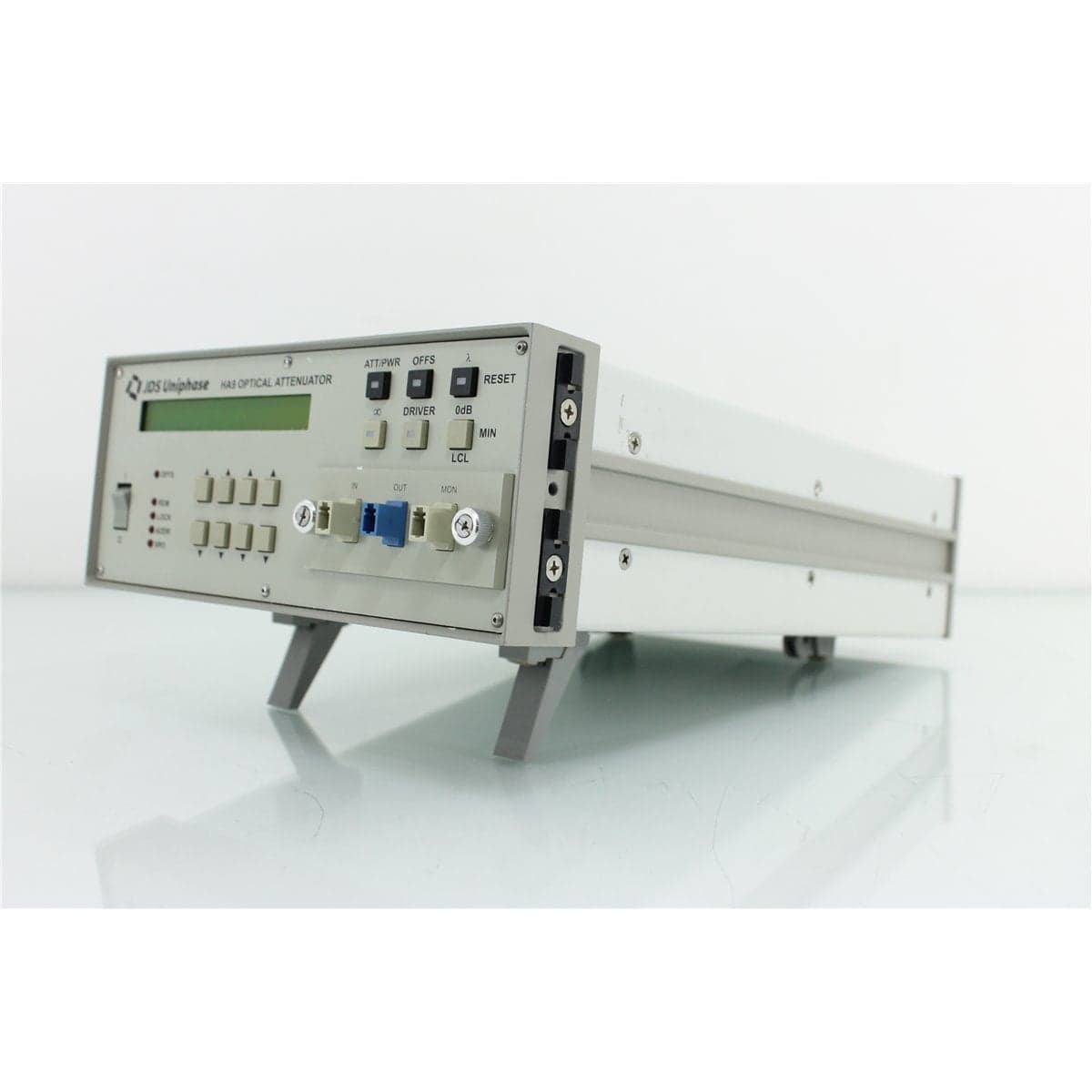
JDS · HA97-29KLC1
JDS Uniphase HA9 9/125 µm Programmable Optical Attenuator with Front LC Monitor Port
$4,619.20
Price in USD.
- Condition
- New (open box)
- Availability
- In stock · 7 available
- Model
- HA97-29KLC1
- Manufacturer
- JDS
- Category
- Optical Attenuators 9-125
Description
JDS Uniphase HA9 9/125 µm Programmable Optical Attenuator with Front LC Monitor Port
The JDS Uniphase HA9 is a high-resolution programmable optical attenuator designed for precise control of optical power in single-mode fiber test systems. This configuration is equipped for 9/125 µm single-mode fiber and features front-panel LC optical connections with a monitor port for accessing a sampled optical signal.
The HA9 provides a continuous programmable attenuation range of up to 100 dB with 0.01 dB resolution. Its broad 1200 nm to 1700 nm operating wavelength range supports common single-mode telecommunications wavelengths, including applications near 1310 nm, 1480 nm, 1550 nm, 1625 nm, and other wavelengths within the supported range.
The instrument can be operated manually from its front-panel keyboard or remotely through GPIB and RS-232 interfaces. Its SCPI-compatible command set supports integration into automated optical test systems for power meter calibration, loss simulation, bit error rate testing, amplifier characterization, analog transmission measurements, and fiber optic component evaluation.
The front optical monitor port provides access to a sampled portion of the optical signal when the applicable internal tap configuration is installed. This output can be connected to a compatible optical power meter or monitoring receiver to observe optical power during attenuation adjustment. The exact internal tap ratio should be confirmed from the instrument configuration, labeling, or measured optical performance.
Features and Benefits of the JDS Uniphase HA9
- 9/125 µm single-mode configuration: Supports compatible single-mode fiber optic sources, patch cords, components, and measurement systems.
- Front-panel LC connections: Provides compact optical interfaces for convenient access in laboratory, production, and rack-mounted installations.
- Optical monitor port: Allows a sampled optical signal to be connected to compatible monitoring or measurement equipment.
- 100 dB attenuation range: Supports high-dynamic-range optical loss simulation and receiver testing.
- 0.01 dB resolution: Allows precise adjustment of optical attenuation in fine increments.
- High repeatability: Provides ±0.01 dB attenuation repeatability under the documented conditions.
- Broad wavelength range: Operates from 1200 nm to 1700 nm for a wide range of single-mode telecommunications applications.
- Built-in beam block: Provides rapid access to an optical blocking state with greater than 90 dB attenuation.
- Low polarization sensitivity: Provides typical polarization-dependent loss of 0.03 dB and a documented maximum of 0.08 dB.
- Remote automation: Supports GPIB, RS-232, and SCPI-compatible programming commands.
- Front-panel operation: Enables local attenuation control without requiring an external computer.
- Rack-mount compatibility: Supports installation in a standard 19-inch equipment rack using appropriate mounting hardware.
Precision Programmable Optical Attenuation
The HA9 controls the optical power transmitted through a connected single-mode fiber path. The attenuation level can be adjusted continuously from the low-loss setting through a maximum programmable range of 100 dB.
Its 0.01 dB resolution supports applications requiring small, controlled changes in optical power. These include receiver sensitivity measurements, amplifier testing, power meter evaluation, component characterization, and simulation of transmission loss in fiber optic links.
Attenuation accuracy is specified at ±0.1 dB under the documented conditions. The accuracy specification applies up to 60 dB of attenuation for single-mode operation at the calibrated wavelength within ±15 nm.
The complete optical path also includes insertion loss from the installed connectors, internal monitor coupler, optical switch if present, patch cords, adapters, and connected components. These external and optional contributions should be considered when a precise end-to-end power level is required.
1200 nm to 1700 nm Operating Range
The JDS Uniphase HA9 operates across wavelengths from 1200 nm to 1700 nm. This broad range supports many optical test applications involving single-mode fiber and telecommunications components.
The instrument can be used with compatible sources operating near standard wavelengths such as 1310 nm, 1480 nm, 1550 nm, and 1625 nm. It is also suitable for other wavelengths within the supported operating range when the appropriate attenuation calibration and optical connectors are used.
The available attenuation range is a continuous function of wavelength. Measurement and attenuation accuracy should be evaluated at the intended operating wavelength, particularly when the instrument is used near the limits of its wavelength range.
9/125 µm Single-Mode Fiber
This HA9 is configured for 9/125 µm single-mode fiber. It should be connected to compatible single-mode optical sources, detectors, patch cords, amplifiers, and devices under test.
Using mismatched multimode fiber can change optical coupling conditions and produce results that do not represent the intended single-mode test system. All reference cables and measurement paths should use compatible single-mode fiber.
Fiber movement, tight bends, mechanical stress, connector contamination, and incompatible connector polish can affect optical power and measurement repeatability. Patch cords should be routed carefully and secured during precision testing.
Front-Panel LC Optical Connections
The instrument is identified as having LC optical access on the front panel. LC connectors provide a compact interface for connecting the attenuator to compatible fiber optic test cables and equipment.
The connector polish should be confirmed before compatible patch cords are selected. APC and non-angled physical-contact connectors must not be directly intermated because their ferrule geometries are different.
All LC connector end faces should be inspected and cleaned before connection. Dust, oil, residue, and fiber debris can introduce insertion loss, increase reflection, create unstable measurements, and damage mating optical surfaces.
The original HA9 ordering information lists several standard connector formats but does not identify LC as a standard catalog option. The front-panel LC arrangement should therefore be treated as the configuration of the individual instrument rather than a specification that applies to every HA9.
Optical Monitor Port
The front optical monitor port provides access to a sampled portion of the signal when the corresponding internal optical tap is installed. The monitor output can be connected to an optical power meter, photodiode receiver, or other compatible monitoring device.
A monitor port is useful in applications that require the source or attenuator output to be observed while attenuation is changed. It can help identify source drift, confirm optical continuity, support closed-loop test systems, and provide a reference signal for automated measurements.
The available HA9 family configurations included several internal coupler ratios. The exact tap ratio installed in this instrument is not established by the supplied product name and should be confirmed from the unit label, internal configuration record, or optical measurements.
The monitor-port power depends on the input power, internal tap ratio, attenuation setting, wavelength, connector losses, and condition of the optical path. The monitoring detector must be suitable for the resulting optical level.
Optional Internal Coupler Configurations
The HA9 platform supported factory-installed optical couplers that provided an output tap for monitoring applications. Available family options included 2/98, 10/90, 30/70, and 50/50 couplers.
| Available Coupler Option | Nominal Optical Split |
| 2/98 Coupler | Nominal 2% and 98% output paths |
| 10/90 Coupler | Nominal 10% and 90% output paths |
| 30/70 Coupler | Nominal 30% and 70% output paths |
| 50/50 Coupler | Nominal equal-power output paths |
The presence of a monitor port indicates an additional optical path, but it does not by itself identify the installed ratio. A specific tap ratio should not be stated unless it is shown on the instrument or confirmed through optical testing.
Low Polarization-Dependent Loss
The HA attenuator family provides typical polarization-dependent loss of 0.03 dB and a documented maximum of 0.08 dB under the specified conditions.
Low PDL is important because the state of polarization in single-mode fiber can change with fiber movement, temperature, mechanical stress, vibration, and upstream optical components. A polarization-sensitive attenuator could produce changes in transmitted power even when the programmed attenuation remains constant.
The HA9 low-PDL performance supports optical receiver testing, amplifier measurements, analog transmission systems, and other applications in which polarization-related power variation must be limited.
Repeatable Attenuation Control
Attenuation repeatability is specified at ±0.01 dB at constant temperature, wavelength, and polarization state after a 30-minute warm-up.
Repeatability is important when an automated procedure returns to the same attenuation setting several times or compares multiple devices under identical optical conditions.
System repeatability can also be influenced by source stability, connector cleanliness, fiber movement, monitor coupler performance, optical power meter stability, polarization changes, and environmental temperature.
Attenuation Change Time
The HA9 provides an attenuation change time of less than 2.5 seconds across the documented 0 dB to 100 dB range.
This performance supports automated receiver sensitivity sweeps, stepped loss simulations, optical power calibration procedures, and production measurements requiring several programmed attenuation levels.
The total time required for a measurement sequence also depends on communication speed, source and detector settling, software operation, averaging, and the response time of the device under test.
Built-In Beam Block
The built-in beam block provides fast access from any programmed attenuation setting to an optical blocking condition. Beam-block attenuation is greater than 90 dB.
This function can be used to interrupt the optical path without changing the stored attenuation setting. It is useful for zero measurements, receiver dark-state evaluation, optical continuity tests, protection routines, and automated test sequencing.
The beam block provides very high attenuation but should not automatically be treated as a laser safety shutter. Appropriate source controls, protective eyewear, enclosures, and other safety measures remain necessary.
Return Loss Performance
Standard single-mode HA9 configurations provide return loss greater than 45 dB under the documented conditions. Analog configurations provide total discrete reflections better than 60 dB.
Return-loss specifications exclude the effects of installed connectors, switches, or couplers. The complete system reflection performance depends on the individual configuration, connector polish, connector cleanliness, patch cords, internal tap, and connected equipment.
For applications requiring low reflection, all installed LC interfaces and patch cords should be inspected, cleaned, and matched correctly. The return loss of the full optical path should be measured when it is a critical system requirement.
Front-Panel 5 V Driver Control
The HA platform provides a front-panel 5 V driver control connected to the corresponding rear-panel driver interface. The control acts as a toggle for an external switch or a compatible internal switch when installed.
The exact function available on this instrument depends on its installed optical configuration. A monitor coupler provides a passive optical sample, while a switch provides active selection between supported optical paths.
The front-panel control and any associated internal option should be functionally identified before the instrument is integrated into an automated test system.
GPIB and RS-232 Remote Control
The HA9 can be controlled remotely through GPIB or RS-232. These interfaces allow a compatible computer, controller, or automated test platform to set attenuation, activate the beam block, query instrument status, and coordinate measurements with other optical equipment.
The command set is SCPI compatible and supports compatibility with programming approaches developed for the HP 8156A attenuator family.
Remote control is useful for receiver sensitivity characterization, bit error rate testing, optical power sweeps, production screening, amplifier testing, and long automated measurement sequences.
GPIB and RS-232 cables, interface adapters, software, drivers, and automation programs are included only when specifically identified in the product listing.
Typical Applications
- Precise optical power control
- Single-mode fiber link loss simulation
- Optical receiver sensitivity testing
- Bit error rate testing
- Optical power meter linearity evaluation
- EDFA output power characterization
- Analog optical transmission measurements
- High-bit-rate digital system testing
- Optical component characterization
- Telecommunications laboratory measurements
- Automated optical production testing
- Monitor-port optical power tracking
Product Overview
| Brand | JDS Uniphase |
| Model | HA9 |
| Product Category | Programmable Single-Mode Optical Attenuator |
| Fiber Type | 9/125 µm single-mode fiber |
| Optical Interface | Front-panel LC connections |
| Additional Optical Port | Front monitor port |
| Operating Wavelength Range | 1200 nm to 1700 nm |
| Maximum Attenuation Range | 100 dB |
| Remote Interfaces | GPIB and RS-232 |
| Primary Application | Programmable optical power control, loss simulation, and monitored attenuation testing |
Optical Attenuation Specifications
| Specification | Details |
| Operating Wavelength Range | 1200 nm to 1700 nm |
| Attenuation Range | 0 dB to 100 dB |
| Attenuation Resolution | 0.01 dB |
| Attenuation Repeatability | ±0.01 dB |
| Attenuation Change Time | Less than 2.5 seconds across the 0 dB to 100 dB range |
| Attenuation Accuracy | ±0.1 dB under the documented conditions |
| Accuracy Range for Single-Mode Operation | Up to 60 dB of attenuation at the calibrated wavelength ±15 nm |
| Beam-Block Attenuation | Greater than 90 dB |
Single-Mode Optical Performance
| Specification | Details |
| Fiber Type | 9/125 µm single-mode |
| Maximum Base Insertion Loss | Less than 1.5 dB, excluding connectors and installed coupler or switch |
| Standard Single-Mode Return Loss | Greater than 45 dB, excluding connectors and installed options |
| Analog Single-Mode Return Loss | Greater than 60 dB for total discrete reflections, excluding connectors and installed options |
| Typical Polarization-Dependent Loss | 0.03 dB |
| Maximum Polarization-Dependent Loss | 0.08 dB |
| Maximum Optical Input Power | 200 mW |
Control and Interface Specifications
| Specification | Details |
| Local Control | Front-panel keyboard |
| Remote Control | GPIB and RS-232 |
| Programming Command Set | SCPI and HP 8156A compatible |
| Beam-Block Control | Front-panel and supported remote control |
| 5 V Driver | Front-panel control connected to the rear-panel driver interface |
Physical and Environmental Specifications
| Specification | Details |
| Width | 21.2 cm |
| Height | 8.9 cm |
| Depth | 35.5 cm |
| Rack Size | 2U high with compatible 19-inch rack-mount hardware |
| Weight | Approximately 4 kg |
| Operating Temperature | 0 °C to 40 °C |
| Storage Temperature | -40 °C to 60 °C |
| Maximum Humidity | 90% at temperatures up to 40 °C |
| Recommended Recalibration Period | Two years |
Electrical and Compliance Specifications
| Specification | Details |
| Input Voltage | 90 V to 240 V AC |
| Line Frequency | 50 Hz to 60 Hz |
| Maximum Power Consumption | 80 VA |
| Compliance | CE requirements, UL 3101-1, and CAN/CSA-C22.2 No. 1010.1 |
Warm-Up and Measurement Conditions
The HA9 should be allowed to warm up for at least 30 minutes before measurements requiring the documented repeatability are performed.
Attenuation repeatability is specified at constant temperature, wavelength, and polarization state. Changes in any of these conditions can affect the measured optical power.
The source and receiving power meter should also complete their required warm-up periods. The source wavelength should correspond to the attenuator calibration and the power meter wavelength setting.
Reference connections should remain mechanically stable throughout the test sequence. If an optical cable is moved, disconnected, cleaned, or replaced, the reference power should be checked again.
Monitor-Port Verification
The monitor port and main optical path should be tested at the intended operating wavelength before the attenuator is integrated into a measurement system.
A stable single-mode source can be connected to the input while calibrated power meters measure the main and monitor outputs. These readings can be used to identify the path arrangement, estimate the installed tap ratio, and evaluate insertion loss.
Monitor measurements should be repeated at several attenuation settings to determine whether the monitor path is located before or after the variable attenuation section. That relationship should not be assumed without testing or configuration documentation.
Connector Inspection and Cleaning
All front-panel LC interfaces should be inspected before use with a suitable fiber inspection system. Contaminated interfaces should be cleaned using an approved procedure and reinspected before mating.
The mating patch cords must use the correct connector polish and compatible single-mode fiber. Improperly matched connectors can cause high loss, reflection, unstable performance, or physical damage.
Protective dust caps should remain installed whenever the ports are not in use. Dust caps should also be kept clean so contaminants are not transferred back to the optical interfaces.
Comprehensive Functional and Performance Testing
The JDS Uniphase HA9 receives comprehensive functional and performance testing before shipment. Testing may include AC power operation, startup, front-panel display, keyboard controls, attenuation adjustment, beam-block operation, 5 V driver control, GPIB communication, and RS-232 communication.
Optical testing may include continuity through the main path, monitor-port response, minimum insertion loss, attenuation at selected settings, attenuation repeatability, beam-block extinction, and operation at representative single-mode wavelengths.
The installed LC ports may be inspected for contamination, damaged alignment sleeves, loose mounting, worn latches, or other conditions that could affect optical coupling. Fiber routing and internal option operation may also be evaluated when accessible through normal instrument functions.
The exact testing scope depends on the installed monitor coupler, path arrangement, LC connector polish, available single-mode sources, calibrated power meters, return-loss equipment, polarization-control equipment, and communication accessories.
Calibration Before Shipment
When technically applicable and selected, the JDS Uniphase HA9 can be calibrated or performance-verified before shipment. Calibration may include attenuation accuracy, attenuation repeatability, minimum insertion loss, beam-block attenuation, monitor-port response, and remote-control operation.
Optical calibration should use stable single-mode sources, calibrated optical power meters, compatible LC reference cables, and suitable equipment at the wavelength required by the buyer’s application.
Calibration documentation should identify the instrument model, serial number, fiber type, connector configuration, monitor-port arrangement, test wavelength, attenuation points, reference equipment, recorded measurements, and applicable uncertainty.
Buyers requiring formal calibration should specify the desired wavelengths, attenuation levels, monitor-port tests, connector polish, certificate type, recorded results, and measurement uncertainty before purchase.
Buyer Considerations
Buyers should confirm that the unit is a JDS Uniphase HA9 configured for 9/125 µm single-mode fiber with front-panel LC optical ports and a monitor output.
The LC connector polish, internal monitor tap ratio, optical path arrangement, return-loss configuration, and exact number of ports should be verified from the instrument label, product photographs, or optical test results.
The condition of the LC ports, alignment sleeves, optical adapters, display, keypad, beam block, 5 V driver, GPIB interface, RS-232 interface, AC inlet, enclosure, rack hardware, calibration label, and model label should be reviewed before purchase.
Only the programmable attenuator, installed optical options, LC patch cords, adapters, GPIB cable, RS-232 cable, rack hardware, power cord, manuals, calibration records, and accessories specifically identified in the product listing should be considered included.
Why Buy from AssetRelay?
AssetRelay supplies professional equipment and product solutions for fiber optic, telecom, laboratory, production, optical test, photonics, electronic test, RF/microwave, inspection, and technical research applications. The JDS Uniphase HA9 supports engineers, telecommunications laboratories, optical component manufacturers, amplifier developers, production facilities, service organizations, system integrators, and research teams requiring precise programmable optical attenuation.
Buyers should review the product photographs, fiber type, front-panel LC connections, connector polish, monitor-port configuration, attenuation performance, beam-block operation, remote interfaces, calibration status, functional test results, and included accessories before purchase.