
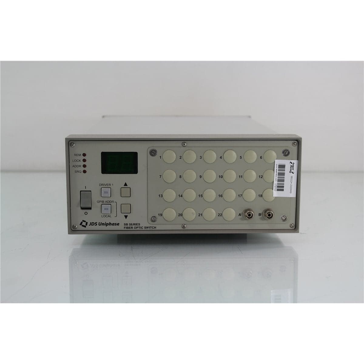
JDS · SB0224-Z000449
JDS Uniphase SB0224-Z000449 2x24 Pigtail Programmable Fiber Optic Switch
$3,992.00
Price in USD.
- Condition
- New (open box)
- Availability
- In stock · 2 available
- Model
- SB0224-Z000449
- Manufacturer
- JDS
- Category
- Optical Switches Other Fiber 2xN
Description
JDS Uniphase SB0224-Z000449 Custom 2x24 Pigtail Programmable Optical Switch
The JDS Uniphase SB0224-Z000449 is a custom programmable fiber optic switch identified with a 2x24 optical configuration and attached pigtail connections. It is designed to automate optical signal routing in laboratory, production, telecommunications, environmental testing, and fiber optic component characterization systems.
The switch allows connected optical sources, detectors, instruments, and devices under test to remain in place while the required optical path is selected electronically. This approach can reduce repeated manual reconnections, improve test throughput, limit connector wear, and help maintain a more consistent optical measurement setup.
The SB Series uses precision optical alignment to connect selected fiber paths. The instrument can support applications involving optical power meters, light sources, programmable attenuators, backreflection meters, transmitters, receivers, environmental chambers, and other compatible fiber optic test equipment.
The Z000449 designation identifies a custom configuration. It does not provide enough information to determine the exact fiber type, wavelength range, connector termination, pigtail location, cable length, return-loss grade, or input-to-output routing logic. These details should be verified from the physical instrument, attached fiber labels, configuration records, or direct optical testing.
Features and Benefits of the JDS Uniphase SB0224-Z000449
- Custom 2x24 optical configuration: Provides programmable routing across the identified two-input and 24-output optical arrangement.
- Optical pigtail connections: Supports integration with connectorized systems, custom test fixtures, optical racks, or fusion-spliced assemblies.
- Programmable channel selection: Allows optical paths to be changed without repeatedly disconnecting test cables.
- Compact SB Series platform: Provides multi-channel optical switching in a benchtop instrument format.
- Precision optical alignment: Uses an internal switching mechanism designed for repeated connection of selected optical channels.
- Automated testing support: Can be integrated with compatible test instruments and computer-controlled measurement systems.
- Reduced connector handling: Helps limit contamination, connector wear, and measurement variation caused by repeated manual mating.
- Multi-device testing: Supports sequential evaluation of several fibers, components, transmitters, receivers, or test points.
- Local operation: Front-panel controls support setup, troubleshooting, channel identification, and manual routing.
- Remote operation: SB Series instruments support computer-controlled channel selection through compatible communication interfaces.
- Custom optical construction: The Z000449 configuration may include application-specific fiber, wavelength, connector, cable, or routing characteristics.
- Professional test integration: Suitable for optical laboratories, manufacturing lines, environmental test systems, and research facilities.
2x24 Optical Switching
The SB0224-Z000449 is identified as a 2x24 optical switch. This channel arrangement provides access to two input paths and 24 output channels for multi-channel optical routing.
The exact relationship between the two inputs and 24 outputs should be verified before the switch is integrated into a test system. Depending on its custom internal design, the instrument may provide independently grouped paths, coordinated routing, adjacent-channel alignment, blocking connections, or another specialized arrangement.
The unit should not be represented as a fully non-blocking optical matrix or as two independent 1x24 switches unless that topology has been confirmed through configuration documentation or optical path mapping.
Custom Z000449 Configuration
The Z000449 suffix indicates that this instrument was manufactured with a custom configuration. Standard SB Series model numbers normally include codes for the number and arrangement of inputs, input port location, output quantity, output port location, fiber type, return-loss option, wavelength range, pigtail length, and connector type.
The custom suffix replaces or supplements part of the standard order-code structure. As a result, individual characteristics cannot be decoded reliably from the model number alone.
The custom configuration may apply to the internal routing arrangement, optical fiber, wavelength optimization, pigtail construction, connector termination, cable length, return-loss performance, channel labeling, mechanical layout, or a combination of these characteristics.
Product photographs, labels, attached fiber markings, original configuration records, and functional test results should be used to document the exact unit.
Optical Pigtail Connections
The SB0224-Z000449 uses optical pigtails for connection to external equipment. Pigtails can simplify integration with a permanent optical rack, test fixture, environmental chamber, production station, or custom fiber assembly.
The attached fibers may have installed connectors or unterminated ends intended for fusion splicing. Connector type and polish should be identified visually and verified before the switch is connected to external equipment.
If the fibers are unterminated, the fiber type must be identified before fusion splicing. Splicing parameters, cleaning procedures, cleave preparation, protection sleeves, and receiving fibers should be selected for the confirmed fiber construction.
The pigtails should be routed with an appropriate bend radius and protected from pulling, twisting, crushing, abrasion, and sharp equipment edges. Mechanical stress near the enclosure exit can increase optical loss or damage the internal fiber attachment.
Fiber Type Verification
The supplied product identification does not specify the fiber type installed in the custom switch. Standard JDS Uniphase SB Series configurations were available with 9/125 µm single-mode, 50/125 µm multimode, 62.5/125 µm multimode, and 100/140 µm multimode fiber.
The installed fiber type should be confirmed from cable markings, original manufacturing records, connector color coding where applicable, optical measurements, or other unit-specific documentation.
Single-mode and multimode fibers should not be treated as interchangeable. Using a mismatched source, reference cable, or receiving fiber can change coupling conditions and produce measurement results that do not represent the intended optical system.
Wavelength Range Verification
The exact operating wavelength range is not established by the SB0224-Z000449 custom model number. Standard SB Series configurations included a 1270 nm to 1670 nm range for supported single-mode applications and multimode configurations covering 850 nm to 1350 nm or 750 nm to 940 nm.
A wavelength range should not be assigned to this unit until its fiber and optical configuration have been confirmed. Performance at 850 nm, 1310 nm, 1550 nm, 1625 nm, or another wavelength should be verified individually when the original configuration documentation is unavailable.
A stable optical source and calibrated power meter can be used to evaluate continuity and insertion loss at the intended wavelength. Measurements made at one wavelength should not automatically be interpreted as confirmation of performance across an entire operating band.
Connector Configuration
Standard SB Series pigtail configurations were available with FC/PC, FC/APC, SC/PC, SC/APC, ST/PC, and unterminated fiber options. The custom Z000449 model may use one of these formats or another specialized termination.
Every installed connector should be identified before the switch is placed into service. The connector family, ferrule polish, fiber type, and key orientation must match the connected patch cord or test instrument.
APC connectors must not be directly intermated with non-angled physical-contact connectors. Incompatible ferrule geometries can produce high insertion loss, poor return loss, unstable transmission, and physical damage.
Optical Path Mapping
A complete input-to-output path map should be created before automated operation begins. Mapping is particularly important for this unit because the custom model number does not define the internal routing logic.
A compatible optical source can be connected to the first input while a calibrated optical power meter monitors each possible output. The switch should be stepped through every available position, and each active output should be recorded.
The procedure should then be repeated with the second input. The resulting data should identify all active paths, simultaneous connections, blocked positions, adjacent relationships, and unavailable input-to-output combinations.
The completed channel map should be used for front-panel operation, cable labeling, automation software, and future maintenance. Fiber color or physical bundle position alone should not be considered definitive channel identification.
Automated Component Testing
The SB0224-Z000449 can support automated testing of multiple fiber optic components using a shared source and measurement instrument. Devices under test can remain connected to assigned pigtails while software selects each required optical path.
A typical automated sequence selects a switch position, allows the optical path to settle, acquires a reading from the connected measurement instrument, records the result, and advances to the next channel.
This method is useful for insertion-loss testing, optical power measurements, source evaluation, receiver testing, component screening, environmental testing, and production quality control.
Transmitter and Receiver Testing
The optical switch can route a compatible transmitter or source to several receivers, fibers, or test points. It can also route multiple optical outputs toward a shared detector or measurement instrument, depending on the confirmed internal configuration.
Receiver testing may combine the switch with a programmable optical attenuator, optical power meter, and bit error rate test equipment. Transmitter testing may use the switch to route optical outputs to a detector, spectrum analyzer, backreflection meter, or other compatible instrument.
The optical power applied to every input and connected instrument must remain within the safe operating limits of the confirmed switch configuration and external equipment.
Environmental Component Testing
Pigtail optical switches are useful in environmental test systems because devices can remain inside a temperature chamber while the external switch and measurement equipment select the required optical path.
This arrangement can reduce the number of instruments required to monitor several components during temperature cycling, aging, burn-in, or long-duration stability testing.
Fiber routing through an environmental chamber should prevent sharp bends, crushing, tension, condensation exposure, and movement that could affect optical transmission independently of the device under test.
Channel-Specific Referencing
Each optical path may introduce a different insertion loss. Precision measurements should therefore use channel-specific reference values rather than assuming that every switch position has identical transmission.
A reference table can be created by measuring each confirmed path with a stable source and calibrated detector. The reference data should identify the input, output, wavelength, optical power, connector arrangement, and measurement date.
When a connector is cleaned, replaced, repaired, or reterminated, the affected path should be referenced again. Pigtail movement and fiber stress can also change the measured transmission.
Local and Remote Operation
JDS Uniphase SB Series switches provide local front-panel controls for selecting optical paths. Local control is useful for initial setup, troubleshooting, path mapping, maintenance, and individual measurements.
The product family also supports remote control for automated operation. The exact communication interfaces fitted to this custom unit should be confirmed from the rear panel and functional test results.
Compatible communication cables, computer interfaces, software, drivers, and automation programs should be considered included only when specifically identified in the listing.
Typical Applications
- Automated fiber optic component testing
- Multi-channel optical signal routing
- Optical transmitter and receiver testing
- Optical source and detector selection
- Insertion-loss measurement automation
- Optical power monitoring
- Backreflection test-system routing
- Fiber cable and assembly evaluation
- Environmental component testing
- Telecommunications system verification
- Production and quality-control testing
- Photonics research and development
Product Overview
| Brand | JDS Uniphase |
| Model | SB0224-Z000449 |
| Product Series | SB Series |
| Product Category | Programmable Fiber Optic Switch |
| Identified Configuration | 2x24 |
| Optical Input Channels | Two, based on the supplied product identification |
| Optical Output Channels | Twenty-four, based on the supplied product identification |
| Optical Interface | Pigtails |
| Custom Configuration | Z000449 |
| Fiber Type | Verify from the individual unit |
| Operating Wavelength | Verify from the individual unit |
| Primary Application | Programmable multi-channel optical routing and automated fiber optic testing |
Confirmed Product Details
| Configuration Item | Confirmed Detail |
| Manufacturer | JDS Uniphase |
| Series | SB programmable fiber optic switch |
| Model Identification | SB0224-Z000449 |
| Channel Identification | 2x24 |
| Connection Style | Optical pigtails |
| Configuration Type | Custom |
Standard SB Series Fiber Options
| Fiber Code | Documented Fiber Type |
| 7 | 9/125 µm single-mode fiber |
| 1 | 50/125 µm multimode fiber |
| 2 | 62.5/125 µm multimode fiber |
| 4 | 100/140 µm multimode fiber |
Standard SB Series Wavelength Options
| Wavelength Code | Documented Operating Range |
| F | 1270 nm to 1670 nm |
| Q | 850 nm to 1350 nm for supported multimode configurations |
| B | 750 nm to 940 nm for supported multimode configurations |
Standard SB Series Connector Options
| Connector Code | Documented Connector Type |
| FP | FC/PC |
| FA | FC/APC for supported single-mode configurations |
| SC | SC/PC |
| SU | SC/APC for supported single-mode configurations |
| SP | ST/PC |
| NC | No connector |
Standard SB Series Port and Cable Options
| Configuration Item | Documented Options |
| Input Port Location | Front bulkheads, front pigtails, or rear pigtails, depending on configuration |
| Output Port Location | Front bulkheads, front pigtails, or rear pigtails, depending on configuration |
| Pigtail Cable Lengths | 1 m, 3 m, 5 m, or 9 m in standard configurations |
| Bulkhead Cable Code | 000, not applicable to pigtail length |
| Return-Loss Options | Standard or analog, depending on configuration |
Configuration Details Requiring Verification
| Item | Required Verification |
| Internal Routing Architecture | Map both inputs across all available output positions |
| Fiber Type | Identify single-mode or multimode fiber and its core/cladding dimensions |
| Wavelength Range | Confirm the intended optical operating band |
| Pigtail Exit Location | Confirm front-panel or rear-panel routing |
| Pigtail Length | Measure the attached fiber cables |
| Connector Type | Identify the connector family fitted to each pigtail |
| Connector Polish | Confirm PC or APC before mating |
| Return-Loss Grade | Confirm standard, analog, or custom configuration |
| Optical Performance | Verify insertion loss, repeatability, crosstalk, and return loss through testing |
Installation and Fiber Handling
The switch should be placed on a stable bench or installed using compatible rack hardware. Adequate ventilation should be maintained around the enclosure, and the instrument should be protected from excessive dust, moisture, vibration, and rapid temperature changes.
Attached fiber bundles should be supported without placing tension on the pigtail exits. Tight cable ties, sharp bends, and concentrated pressure should be avoided.
Each fiber should be clearly labeled according to the verified optical path map. Labels should remain readable after the switch is installed in its final test system.
Optical connectors should be inspected and cleaned before use. Protective caps should remain installed whenever connectorized pigtails are not connected.
Comprehensive Functional and Performance Testing
The JDS Uniphase SB0224-Z000449 receives comprehensive functional and performance testing before shipment. Evaluation may include AC power operation, startup, display condition, front-panel controls, channel selection, switch movement, and available remote communication functions.
Optical testing may include identification of the two input paths, mapping of all accessible output channels, continuity verification, blocked-path identification, repeated switching, and insertion-loss comparison at a wavelength compatible with the identified fiber.
The attached pigtails, connectors, fiber coatings, strain relief, enclosure exits, channel labels, front-panel controls, communication interfaces, AC inlet, enclosure, and ventilation openings may be inspected for contamination, damage, or excessive wear.
The exact testing scope depends on the custom routing arrangement, fiber type, wavelength range, connector termination, accessible paths, calibrated optical sources, power meters, return-loss equipment, and supporting test accessories.
Buyer Considerations
Buyers should confirm the complete identification as JDS Uniphase SB0224-Z000449 and compare the listed 2x24 configuration with the physical fiber arrangement and channel labels.
The custom Z000449 designation means that standard assumptions should not be made about routing topology, fiber type, wavelength, connector format, pigtail length, return-loss grade, or optical performance.
The listing should identify whether the pigtails are connectorized or unterminated. When connectors are present, the connector type and polish should be documented.
Only the optical switch, attached pigtails, installed connectors, protective caps, power cord, communication cables, rack hardware, software, manuals, test records, and accessories specifically identified in the product listing should be considered included.
Why Buy from AssetRelay?
AssetRelay supplies professional equipment and product solutions for fiber optic, telecom, laboratory, production, optical test, photonics, inspection, cleaning, electronic test, RF/microwave, and technical research applications. The JDS Uniphase SB0224-Z000449 supports component manufacturers, telecommunications laboratories, production facilities, system integrators, service organizations, universities, and research teams requiring custom multi-channel optical switching.
Buyers should review the product photographs, complete custom model label, two-input and 24-output identification, pigtail condition, optical path map, fiber type, connector configuration, remote-control operation, functional test results, and included accessories before purchase.