
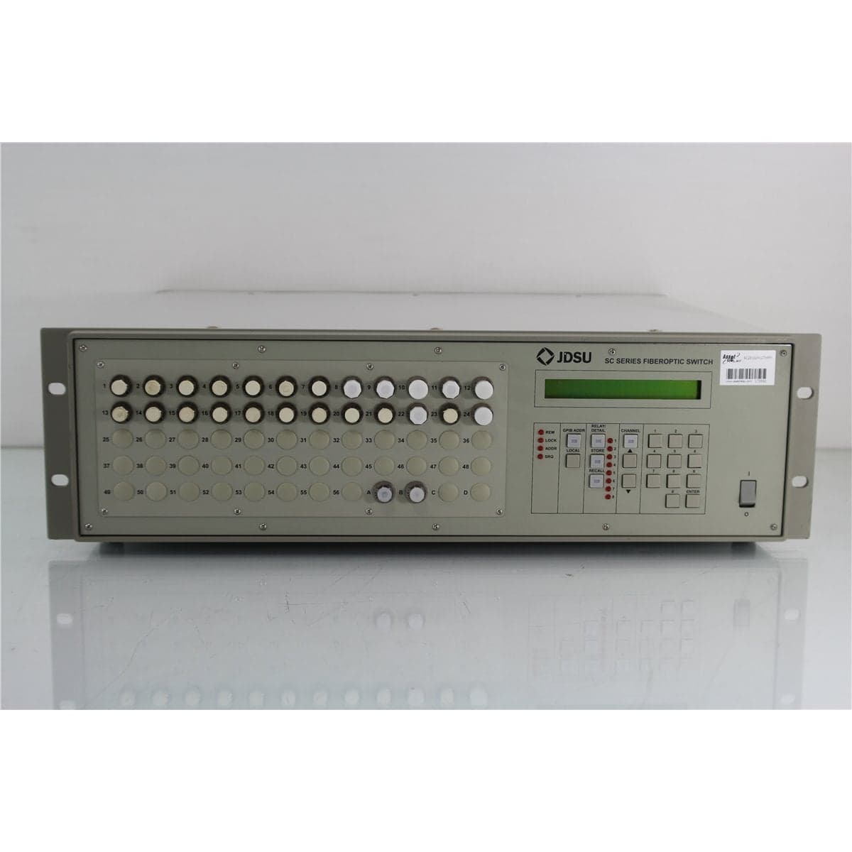
JDS · SC2E1024127XFFP
JDS Uniphase SC2E10241+27XF000FP 2x24 9/125 µm FC/PC Programmable Optical Switch
$3,992.00
Price in USD.
- Condition
- New (open box)
- Availability
- In stock
- Model
- SC2E1024127XFFP
- Manufacturer
- JDS
- Category
- Optical Switches 9-125 2xN
Description
JDS Uniphase SC2E10241+27XF000FP 2x24 FC/PC Programmable Optical Switch
The JDS Uniphase SC2E10241+27XF000FP is a rack-mount programmable optical switch designed for automated routing of single-mode optical signals. This configuration provides two input channels and 24 output channels through front-panel FC/PC bulkhead connectors. It uses 9/125 µm single-mode fiber and operates across wavelengths from 1270 nm to 1670 nm.
The switch uses the JDS Uniphase E configuration. This non-blocking arrangement allows either input to align with a selected output while the second input is aligned with the corresponding adjacent output according to the internal channel sequence. This architecture supports coordinated two-channel routing for component testing, optical system development, manufacturing, laboratory measurement, and telecommunications applications.
Expanded-beam lens technology and precision stepper-motor positioning are used to align the optical channels. Collimating lenses help provide low insertion loss and repeatable optical coupling, while internal temperature control of the switching mechanism supports stable performance during extended operation.
The SC2E10241+27XF000FP can be operated locally from its front-panel keys and numeric keypad or remotely through GPIB and serial RS-232 interfaces. It can be integrated with optical sources, power meters, spectrum analyzers, attenuators, receivers, amplifiers, and other test instruments to automate high-channel-count optical measurements.
Features and Benefits of the JDS Uniphase SC2E10241+27XF000FP
- 2x24 optical configuration: Provides two optical inputs and 24 output channels for high-channel-count routing applications.
- Non-blocking E configuration: Connects a selected input to a selected output while aligning the second input with the corresponding adjacent output.
- Single-mode optical paths: Uses 9/125 µm fiber for compatible telecom, laboratory, production, and photonics systems.
- Broad wavelength coverage: Operates from 1270 nm to 1670 nm, covering common 1310 nm, 1490 nm, 1550 nm, and 1625 nm applications.
- Front-panel FC/PC bulkheads: Provides secure threaded interfaces for both input and output channels.
- Low insertion loss: Provides 0.5 dB typical and 1.0 dB maximum internal insertion loss for the documented single-mode E configuration.
- High return loss: Provides at least 65 dB typical internal return loss in the standard single-mode configuration.
- Low polarization-dependent loss: Offers typical PDL of 0.03 dB for supported single-mode E-configuration paths.
- Repeatable channel selection: Provides typical sequential switching repeatability of ±0.005 dB.
- High channel isolation: Provides maximum single-mode crosstalk of -80 dB.
- Long mechanical life: Rated for more than 80 million switching cycles.
- Local and remote operation: Supports front-panel control, GPIB, and serial RS-232 interfaces.
2x24 Optical Routing
The SC2E10241+27XF000FP provides two optical input channels and 24 output channels. This arrangement supports systems that must route two sources, instruments, or optical paths across multiple devices under test or monitoring points.
A programmable switch reduces the need to disconnect and reconnect optical patch cords manually. Fewer manual connections can improve workflow efficiency, reduce connector wear, and help maintain a consistent optical test arrangement.
The switch can be used to route optical signals between sources and multiple components, between several test points and measurement instruments, or within automated systems that evaluate many fiber assemblies or optical devices in sequence.
Non-Blocking E Configuration
The E configuration allows any input to connect with a selected output while other inputs are aligned to adjacent outputs. For this two-input configuration, selecting the relationship between one input and one output also establishes the corresponding position of the second input.
This operating arrangement differs from a fully independent matrix switch. The two optical paths follow the switch’s defined adjacent-channel sequence rather than moving independently to unrelated outputs.
The E configuration is useful for paired measurements, comparison testing, dual-source routing, and applications that require two optical paths to advance together through an ordered bank of outputs.
The internal channel relationship should be mapped before the switch is incorporated into automated software. Device assignments and output numbering should follow the actual channel sequence established by the instrument.
Expanded-Beam Switching Technology
The switch operates using expanded-beam lens technology. Optical signals are collimated, aligned with selected channels through precision mechanical positioning, and coupled into the corresponding output fibers.
Using collimating lenses helps reduce insertion loss and improves repeatability compared with direct mechanical contact between internal fiber ends. The optical system is bidirectional in its passive transmission characteristics, although the supplied standard return-loss configuration is not specifically identified as a bidirectional ordering option.
A precision stepper motor positions the optical channels. Internal temperature control stabilizes the mechanism to help maintain optical alignment as environmental conditions change.
1270 nm to 1670 nm Wavelength Range
The wavelength code F identifies an operating range from 1270 nm to 1670 nm. This broad range supports many single-mode fiber optic systems used in telecommunications, optical test, monitoring, and photonics development.
Compatible applications include optical measurements near 1310 nm, 1490 nm, 1550 nm, and 1625 nm. Other wavelengths within the supported range can also be routed when the optical sources, patch cords, devices under test, and measurement equipment are compatible.
The SC2E10241+27XF000FP is a passive optical routing instrument. It does not amplify, regenerate, modulate, detect, or convert the wavelength of the transmitted signal.
9/125 µm Single-Mode Fiber
The fiber code 7 identifies 9/125 µm single-mode fiber. The switch should be used with compatible single-mode sources, detectors, test instruments, and optical patch cords.
Using multimode fiber in a single-mode test path can alter coupling conditions and produce results that do not represent the intended system. Reference cables and measurement paths should therefore use compatible 9/125 µm fiber.
Single-mode patch cords should be routed with a suitable bend radius and protected from pulling, crushing, twisting, and repeated movement. Mechanical stress can change optical loss and polarization conditions.
Front-Panel FC/PC Bulkhead Connections
The input port code 1 and output port code 1 identify front-panel bulkhead interfaces. The FP connector code identifies FC/PC connectors on the optical channels.
The front panel provides two input connectors and 24 output connectors for a total of 26 FC/PC optical interfaces. The threaded FC coupling mechanism provides secure attachment for laboratory and rack-mounted test systems.
FC/PC patch cords must be used with the installed interfaces. FC/APC connectors should not be directly connected to FC/PC bulkheads because the different ferrule geometries can produce excessive loss and damage the mating surfaces.
Low Insertion Loss
The documented single-mode E configuration provides typical internal insertion loss of 0.5 dB and maximum insertion loss of 1.0 dB. These values apply to the optical switch mechanism and exclude external connector losses.
Low insertion loss helps preserve the optical power budget when the switch is installed between a source and device under test or between a device and measurement instrument.
The complete path loss also includes the FC/PC connector pairs, patch cords, adapters, and other components in the test setup. Each input-to-output path should be referenced separately when precise loss measurements are required.
High Return Loss
The standard single-mode E configuration provides typical internal return loss of at least 65 dB and a documented minimum of 60 dB. The part-number code X identifies the standard return-loss configuration.
High return loss helps reduce optical reflections toward lasers, amplifiers, transmitters, and other reflection-sensitive components. The stated switch specifications exclude connector contributions.
Complete system return loss depends on the FC/PC connectors, patch cords, adapters, connected devices, and cleanliness of every optical interface.
Low Polarization-Dependent Loss
Polarization-dependent loss is specified at 0.03 dB typical and 0.07 dB maximum for the single-mode E configuration. Low PDL helps reduce changes in transmitted power as the input state of polarization varies.
This performance is valuable in optical component testing, amplifier measurements, source routing, and other applications where polarization-related loss can affect measurement consistency.
The complete test system may have additional PDL from patch cords, connector adapters, couplers, and devices under test. System-level characterization may be required when polarization sensitivity is critical.
Switching Repeatability
Typical sequential switching repeatability is ±0.005 dB, with a documented maximum of ±0.01 dB. Sequential switching refers to movement through channels in their normal ordered sequence.
Typical random switching repeatability is ±0.02 dB, with a documented maximum of ±0.04 dB. Random switching refers to changes between nonadjacent or independently requested switch positions.
The published repeatability values are based on stabilized optical and environmental conditions. Measurement results can also be affected by source stability, detector noise, connector condition, wavelength, polarization, and patch-cord movement.
Insertion-Loss Stability
Insertion-loss stability is specified at ±0.03 dB typical and ±0.05 dB maximum. The specification describes the drift of a channel relative to a reference channel with a ±3 °C ambient-temperature deviation over seven days.
The internally temperature-controlled switching mechanism supports stable channel alignment. The switch and connected optical equipment should still be allowed to reach thermal equilibrium before reference measurements are established.
Channel Crosstalk
Maximum crosstalk for the single-mode switch is specified at -80 dB. This isolation helps reduce leakage from unselected optical channels into the active measurement path.
High isolation is useful when low optical levels are measured near stronger sources or when several connected channels terminate at sensitive detectors and receivers.
Complete system crosstalk can also include contributions from external components, test fixtures, detector limitations, stray optical signals, and instrument noise.
Switching Speed
The documented switching time is 300 ms for one channel movement and 12 ms for each additional channel. Total switching time depends on the distance between the current and requested positions.
Automated software should allow the switch mechanism to complete its movement and settle before the connected optical instrument records a measurement.
The switching speed is suitable for automated production measurements, component characterization, channel monitoring, source routing, and laboratory test sequences.
Mechanical Service Life
The SC Series switch is rated for more than 80 million switching cycles. This supports repeated channel selection in automated manufacturing, qualification, and laboratory systems.
Actual service life can depend on operating environment, switching patterns, temperature, maintenance history, mechanical condition, and accumulated use.
Optical Input Power
Maximum optical input power is specified at 300 mW. The output of connected lasers, optical amplifiers, and other high-power sources should be verified before connection.
The maximum optical input specification applies to the switch path and does not establish a safe input level for connected receivers or power meters. Each instrument connected to an output must remain within its own optical input limits.
Suitable external attenuation should be used when the source level could exceed the safe operating range of the switch or connected measurement equipment.
Local Front-Panel Control
The SC2E10241+27XF000FP can be controlled using front-panel keys and a numeric keypad. Local operation supports channel selection, setup, troubleshooting, path verification, and manual laboratory routing.
Front-panel controls allow the switch to be operated without an external computer. The displayed switch position should be compared with the physical port map when identifying optical paths.
GPIB and RS-232 Remote Control
The switch provides GPIB and serial RS-232 interfaces for remote channel selection and system integration. A compatible computer or test controller can coordinate the switch with other optical and electronic instruments.
Remote control is useful for repetitive test sequences involving optical sources, power meters, spectrum analyzers, attenuators, receivers, amplifiers, and multiple devices under test.
GPIB and RS-232 cables, software, computer interfaces, drivers, and automation programs should be considered included only when specifically identified in the product listing.
External Switch Drivers
The SC platform provides four open-collector drivers for controlling compatible external switch modules or related test equipment. Each output supports a maximum sink current of 100 mA.
The driver connections can help coordinate external routing or control functions with the optical switch position. External loads must remain within the supported electrical limits.
The rear-panel pinout and requirements of the connected device should be verified before the driver outputs are used.
Typical Applications
- Automated fiber optic component testing
- Two-input, multi-output optical signal routing
- Single-mode source distribution
- Optical power meter channel selection
- Optical transmitter and receiver testing
- WDM and DWDM component characterization
- Optical amplifier testing
- Fiber optic cable and assembly testing
- Telecommunications system verification
- Production and quality-control testing
- Laboratory research and development
- High-channel-count optical monitoring
Product Overview
| Brand | JDS Uniphase |
| Model | SC2E10241+27XF000FP |
| Product Series | SC Series |
| Product Category | Rack-Mount Programmable Optical Switch |
| Switch Configuration | 2x24 E configuration |
| Input Channels | Two |
| Output Channels | 24 |
| Fiber Type | 9/125 µm single-mode fiber |
| Connector Type | FC/PC |
| Port Location | Front-panel bulkheads |
| Operating Wavelength Range | 1270 nm to 1670 nm |
| Return-Loss Configuration | Standard |
| Primary Application | Programmable two-input optical routing across 24 single-mode output channels |
Part Number Configuration
| Part Number Element | Configuration |
| SC | SC Series rack-mount programmable optical switch |
| 2E | Two input channels with E configuration |
| Input Port Code 1 | Input bulkheads on the front panel |
| Output Code 024 | 24 output channels |
| Output Port Code 1 | Output bulkheads on the front panel |
| Fiber Code 7 | 9/125 µm single-mode fiber |
| Return-Loss Code X | Standard return-loss configuration |
| Wavelength Code F | 1270 nm to 1670 nm |
| Cable-Length Code 000 | Not applicable to the front-panel bulkhead configuration |
| Connector Code FP | FC/PC connectors |
Optical Specifications
| Specification | Typical | Documented Limit |
| Insertion Loss | 0.5 dB | 1.0 dB maximum, excluding connectors |
| Return Loss | At least 65 dB | 60 dB minimum, excluding connectors |
| Polarization-Dependent Loss | 0.03 dB | 0.07 dB maximum |
| Insertion-Loss Stability | ±0.03 dB | ±0.05 dB maximum |
| Sequential Switching Repeatability | ±0.005 dB | ±0.01 dB maximum |
| Random Switching Repeatability | ±0.02 dB | ±0.04 dB maximum |
| Single-Mode Crosstalk | Not specified | -80 dB maximum |
Switching Specifications
| Specification | Details |
| Switching Technology | Expanded-beam optical system with precision stepper-motor positioning |
| Switch Configuration | Two-input E configuration |
| First-Channel Switching Time | 300 ms |
| Each Additional Channel | 12 ms |
| Mechanical Lifetime | More than 80 million switching cycles |
| Maximum Optical Input Power | 300 mW |
Control Specifications
| Control Function | Details |
| Local Control | Front-panel keys and numeric keypad |
| Remote Interfaces | GPIB and serial RS-232 |
| External Switch Drivers | Four open-collector outputs |
| Maximum Driver Sink Current | 100 mA |
Physical and Environmental Specifications
| Specification | Details |
| Width | 48 cm |
| Height | 13 cm |
| Depth | 37 cm, excluding handles |
| Weight | Approximately 9 kg |
| Operating Temperature | 0 °C to 55 °C |
| Storage Temperature | -40 °C to 70 °C |
| Maximum Humidity | 95% relative humidity from 0 °C to 55 °C, non-condensing |
Power and Compliance Specifications
| Specification | Details |
| AC Input | 100 V to 240 V AC |
| Line Frequency | 50 Hz to 60 Hz |
| Maximum Power Consumption | 100 VA |
| Compliance | CE requirements, UL 3101-1, and CAN/CSA-C22.2 No. 1010.1 |
Installation and Measurement Considerations
The switch should be allowed to stabilize for at least one hour before measurements requiring the documented optical performance are performed. Connected sources and measurement instruments should also complete their recommended warm-up periods.
The two-input E-configuration sequence should be mapped and documented before devices are assigned to the output channels. Automated software must account for the corresponding movement of both input paths.
Each input-to-output path should be referenced using the same source, wavelength, patch cords, and detector intended for the final measurements. Connector and patch-cord losses should be separated from the internal switch loss when required.
The switch should be installed with adequate ventilation and protected from excessive dust, moisture, vibration, and rapid ambient-temperature changes.
FC/PC Connector Care
All front-panel FC/PC bulkheads should be inspected before use. Contaminated interfaces should be cleaned using an approved fiber optic cleaning procedure and reinspected before mating.
Clean connectors help preserve insertion loss, return loss, stability, and switching repeatability. A contaminated patch cord can transfer debris to multiple switch ports during an automated test sequence.
Protective caps should remain installed on unused channels. Dust caps should also remain clean so they do not transfer contamination back to the optical interfaces.
Comprehensive Functional and Performance Testing
The JDS Uniphase SC2E10241+27XF000FP receives comprehensive functional and performance testing before shipment. Mainframe evaluation may include AC power operation, startup, display response, keypad operation, channel selection, GPIB communication, RS-232 communication, and available external driver functions.
Optical testing may include continuity through supported positions, mapping of both input paths, E-configuration sequence verification, through-path insertion-loss comparison, switching repeatability, channel isolation, and operation at representative single-mode wavelengths.
The 26 front-panel FC/PC bulkheads may be inspected for contamination, damaged threads, worn alignment sleeves, loose mounting, missing protective caps, or other conditions that could affect optical coupling.
The exact testing scope depends on connector condition, available single-mode sources, calibrated optical power meters, return-loss equipment, polarization-control equipment, communication accessories, and the quantity of channels selected for detailed testing.
Calibration Before Shipment
When technically applicable and selected, the JDS Uniphase SC2E10241+27XF000FP can be calibrated or performance-verified before shipment. Evaluation may include path mapping, insertion loss, return loss, switching repeatability, crosstalk, switching time, and operation at selected wavelengths within the 1270 nm to 1670 nm range.
Calibration should identify each input, output, switch position, test wavelength, reference patch cord, optical source, power meter, measurement procedure, recorded value, and applicable uncertainty.
Buyers requiring formal calibration should specify the measurement wavelengths, channels, optical parameters, quantity of tested paths, certificate type, recorded results, and required measurement uncertainty before purchase.
Buyer Considerations
Buyers should confirm the complete model number as JDS Uniphase SC2E10241+27XF000FP. The configuration identifies a two-input, 24-output E-configuration switch with front-panel FC/PC bulkheads, 9/125 µm single-mode fiber, standard return-loss performance, and a 1270 nm to 1670 nm wavelength range.
The relationship between the two E-configuration paths should be understood before the switch is installed. This model does not provide two completely independent input-to-output routing assignments.
The condition of the FC/PC bulkheads, alignment sleeves, connector threads, display, keypad, GPIB port, RS-232 port, external driver interface, cooling system, AC inlet, enclosure, handles, model label, and calibration label should be reviewed.
Only the programmable optical switch, power cord, FC/PC patch cords, protective caps, GPIB cable, RS-232 cable, rack hardware, software, manuals, calibration records, and accessories specifically identified in the product listing should be considered included.
Why Buy from AssetRelay?
AssetRelay supplies professional equipment and product solutions for fiber optic, telecom, laboratory, production, optical testing, photonics, laser control, electronic testing, RF/microwave, inspection, and technical research applications. The JDS Uniphase SC2E10241+27XF000FP provides programmable two-input optical routing for telecommunications laboratories, component manufacturers, optical system developers, production facilities, universities, service organizations, and research teams.
Buyers should review the product photographs, complete configuration code, FC/PC port condition, channel labeling, E-configuration routing sequence, remote interfaces, calibration status, functional test results, and included accessories before purchase.