
JDS · mOSWC111C024BS
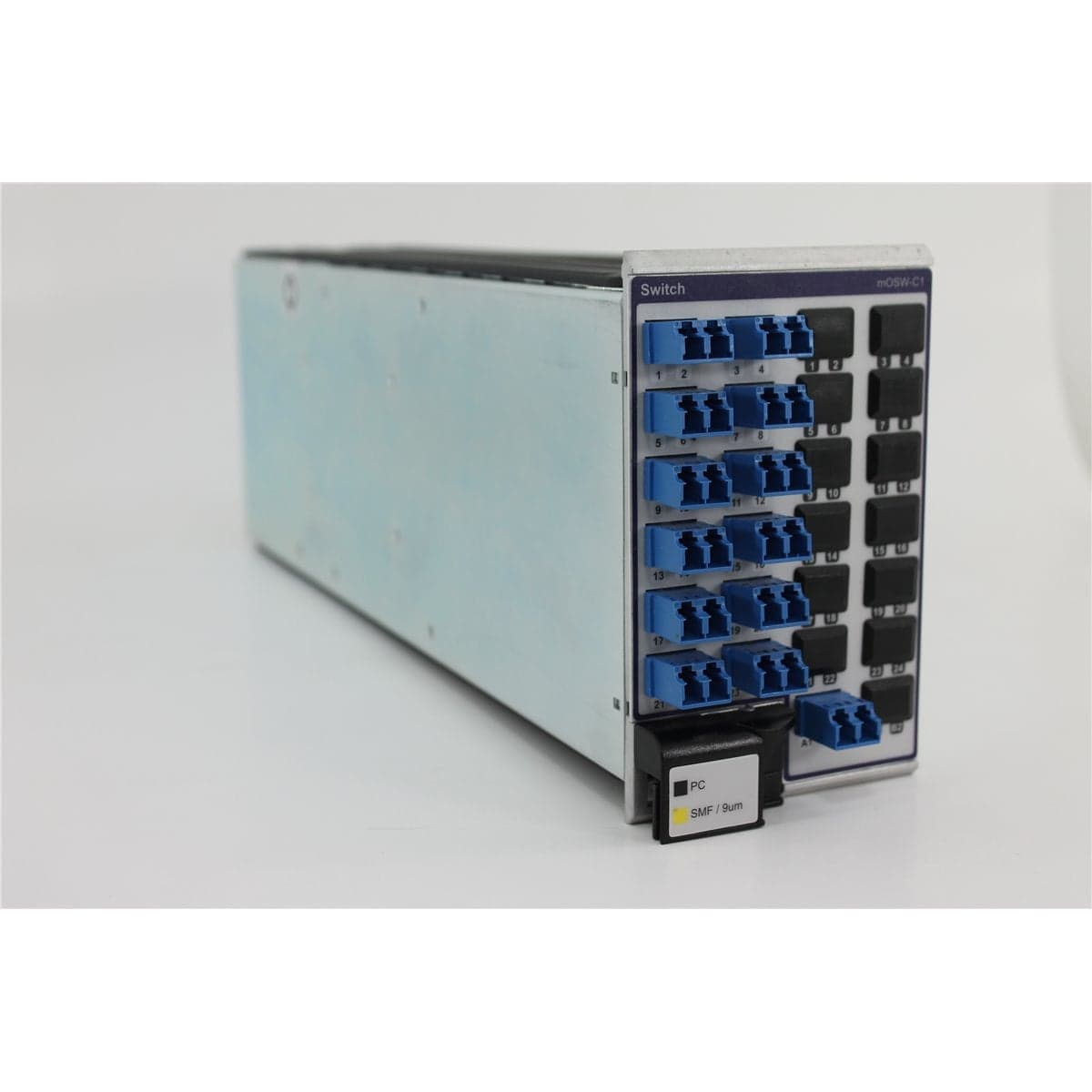
JDSU mOSW-C111C024BS-M100-MLC 1x24 Single-Mode Optical Switch
$4,472.00
Price in USD.
- Condition
- New (open box)
- Availability
- In stock · 5 available
- Model
- mOSWC111C024BS
- Manufacturer
- JDS
- Category
- Optical Switches
Description
JDSU mOSW-C111C024BS-M100-MLC 1x24 Single-Mode Optical Switch
The JDSU mOSW-C111C024BS-M100-MLC is a modular 1x24 optical switch designed for automated single-mode fiber routing in compatible JDSU MAP Series test platforms. The module connects one common optical input to any one of 24 selectable output channels, allowing optical sources, measurement instruments, devices under test, and fiber paths to be selected through the host system.
This exact configuration uses 9 µm single-mode fiber and front-panel LC/PC bulkhead connectors. The bulkhead interface provides direct access to the common port and switch channels using compatible LC/PC single-mode patch cords. The module occupies two adjacent slots in a compatible MAP-230B or MAP-280 chassis.
Automated channel selection reduces the need to move optical patch cords repeatedly during testing. This can improve test consistency, reduce connector handling, minimize port-selection errors, and increase throughput in production and laboratory applications.
The mOSW-C111C024BS-M100-MLC is a plug-in module and does not operate independently. A compatible JDSU MAP chassis provides electrical power, module recognition, local control, system software, and remote communication.
Features and Benefits of the JDSU mOSW-C111C024BS-M100-MLC
- 1x24 switch configuration: Routes one common optical input to any one of 24 selectable output channels.
- Single independent switch: Provides one complete 1x24 optical switching path within the module.
- 9 µm single-mode fiber: Supports compatible single-mode optical sources, devices, patch cords, and measurement instruments.
- LC/PC connectors: Uses compact physical-contact LC bulkhead interfaces on the module front panel.
- Bulkhead termination: Allows compatible patch cords to connect directly to the module without permanently attached pigtails.
- Automated fiber routing: Reduces repeated manual reconnection during multiport optical testing.
- Repeatable test paths: Allows the same source-to-channel connections to be recreated through host-system commands.
- Protocol-independent operation: Routes compatible signals optically without interpreting the transmitted data format.
- Bit-rate-independent switching: Supports compatible analog and digital optical signals without electrical regeneration within the switch path.
- Two-slot module: Occupies two adjacent positions in a compatible MAP-230B or MAP-280 chassis.
- Manufacturing automation: Supports repeatable test sequences for optical components, transceivers, modules, and line cards.
- Shared-instrument routing: Allows multiple devices or fiber paths to use a common optical source or measuring instrument sequentially.
1x24 Optical Switching Architecture
The mOSW-C111C024BS-M100-MLC provides one common optical port and 24 selectable channel ports. The host system commands the module to establish an optical path between the common port and the required channel.
Only one of the 24 channel paths is selected at a time. The module does not divide the optical input among all outputs simultaneously and should not be described as a 1x24 optical splitter.
In a typical source-routing configuration, an optical source connects to the common port and the switch directs the source to one device under test at a time. The optical path may also be arranged so that multiple device outputs are selected sequentially for measurement by a shared instrument.
9 µm Single-Mode Fiber Configuration
The M100 option identifies a 9 µm single-mode fiber configuration. The module should be used with compatible single-mode patch cords, sources, receivers, optical power meters, spectrum analyzers, attenuators, and devices under test.
Maintaining single-mode fiber throughout the optical path helps preserve the intended launch condition and supports consistent optical measurements. Multimode patch cords should not be substituted when controlled single-mode operation is required.
Fiber routing should maintain an appropriate bend radius and avoid pulling, twisting, crushing, or placing strain on the LC bulkhead connectors. Mechanical changes in patch-cord routing can affect optical loss and measurement repeatability.
LC/PC Front-Panel Bulkhead Connectors
The MLC option identifies LC/PC optical connectors. These compact connectors use non-angled physical-contact ferrules and are suitable for dense optical test-system configurations.
The bulkhead arrangement allows patch cords to connect directly to the front of the module. This provides flexibility when test cables, devices, or channel assignments must be changed.
Only compatible LC/PC patch cords should be connected to the module. LC/APC connectors must not be directly intermated with LC/PC bulkheads because angled and non-angled ferrules have incompatible geometries.
Automated Optical Test Integration
The optical switch can be incorporated into automated test sequences controlled through the compatible MAP chassis. The test system can select a channel, configure supporting equipment, perform a measurement, save the result, and continue to another channel without manual cable changes.
This workflow can increase throughput in optical manufacturing and qualification systems containing multiple devices, channels, transceivers, line cards, or fiber paths.
Automated switching can also reduce handling of optical connectors. Reducing the number of manual connections helps limit contamination, connector wear, incorrect port selection, and inconsistencies between repeated measurements.
Compatible MAP Test Platforms
This mOSW-C1 configuration is designed for compatible JDSU MAP-230B and MAP-280 optical test-system chassis. The module occupies two adjacent chassis slots.
The host chassis supplies operating power and provides module recognition, local controls, graphical interface functions, software support, and remote communication for automated operation.
Chassis firmware, software revision, available slot space, and module support should be verified before installation. The chassis, controller, software, cables, and other MAP modules are separate unless specifically identified in the product listing.
Typical Applications
- Automated optical component testing
- Single-mode fiber path selection
- Optical transceiver evaluation
- Multiport device characterization
- Shared optical source routing
- Shared optical measurement-instrument routing
- Optical line-card testing
- Manufacturing test automation
- Reliability and environmental testing
- Fiber network simulation
- Laboratory photonics automation
- Telecommunications research and development
Product Overview
| Brand | JDSU |
| Model | mOSW-C111C024BS-M100-MLC |
| Product Family | mOSW-C1 LightDirect MAP Series |
| Product Category | Modular Single-Mode Optical Switch |
| Switch Configuration | 1 input x 24 selectable outputs |
| Independent Switches | One |
| Fiber Type | 9 µm single-mode fiber |
| Connector Type | LC/PC |
| Termination Style | Front-panel bulkhead connectors |
| Module Width | Two MAP chassis slots |
| Compatible Chassis | JDSU MAP-230B and MAP-280 |
| Standalone Operation | Not supported |
| Primary Application | Automated single-mode optical routing between one common port and 24 selectable channels |
Model Number Breakdown
| Model Element | Configuration |
| mOSW-C1 | LightDirect MAP Series optical switch module |
| 1 | One independent optical switch |
| 1C | Single common optical input configuration |
| 024 | Twenty-four selectable output channels |
| B | Front-panel bulkhead termination |
| S | Factory configuration identifier for the supplied module |
| M100 | 9 µm single-mode optical fiber |
| MLC | LC/PC optical connectors |
Configuration Specifications
| Specification | Details |
| Switch Type | Single-input optical channel selector |
| Common Ports | One |
| Selectable Channels | Twenty-four |
| Signal Routing | One common port connected to one selected channel at a time |
| Signal Conversion | No optical-electrical-optical conversion within the switch path |
| Fiber Configuration | M100, 9 µm single-mode fiber |
| Connector Configuration | MLC, LC/PC |
| Optical Termination | Front-panel bulkheads |
| Chassis Space Required | Two adjacent MAP chassis slots |
Port Mapping and System Setup
A complete port map should be created before the switch is placed into automated service. The map should identify the common port, all 24 channel ports, connected instruments, devices under test, fiber paths, and software channel assignments.
Physical port labels should be compared with the channel numbers displayed by the MAP system. A controlled optical source and power meter can be used to verify that each commanded channel corresponds to the intended physical LC/PC bulkhead.
Maintaining an accurate port map helps prevent incorrect signal routing, invalid measurements, unexpected optical exposure, and accidental connection of a high-power source to a sensitive detector.
Installation and Operation
The mOSW-C111C024BS-M100-MLC should be installed in two adjacent slots of a compatible MAP-230B or MAP-280 chassis. The module should be seated securely and recognized by the host platform before optical connections are made.
Clean LC/PC single-mode patch cords should be connected to the common port and required output channels. The cables should be routed with suitable bend radius and strain relief.
Initial testing should be performed using a controlled optical power level. Each switch command should be checked against the corresponding physical output before an automated test sequence begins.
Unused optical ports should remain protected with clean dust caps. The switch should be controlled through the supported local or remote interface provided by the compatible MAP chassis.
Connector Inspection and Cleaning
All LC/PC bulkheads and mating patch cords should be inspected before connection. Contaminated fiber end faces should be cleaned using an approved fiber optic process and reinspected before mating.
Clean interfaces help preserve insertion loss, return loss, switching repeatability, and connector condition. A contaminated patch cord can transfer debris to several switch ports as it is moved through the system.
Only clean protective caps should be installed on unused ports. Dirty caps can transfer contamination directly to the LC/PC bulkhead.
Comprehensive Functional and Performance Testing
The JDSU mOSW-C111C024BS-M100-MLC receives comprehensive functional and performance testing before shipment. Evaluation may include installation in a compatible MAP chassis, module recognition, startup, software control, channel selection, and switching across all 24 output channels.
Optical testing may include common-port continuity, comprehensive port mapping, representative or complete insertion-loss measurements, and channel repeatability using compatible single-mode equipment.
All LC/PC bulkhead connectors, the module faceplate, chassis connector, port labels, enclosure, latches, guide hardware, and model markings may be inspected for contamination, damage, corrosion, deformation, or excessive wear.
The exact testing scope depends on the available compatible chassis, reference patch cords, optical source, calibrated power meter, requested wavelengths, and required channel coverage.
Buyer Considerations
Buyers should confirm the complete model as JDSU mOSW-C111C024BS-M100-MLC. This configuration identifies one 1x24 switch, front-panel bulkhead termination, 9 µm single-mode fiber, and LC/PC connectors.
The module requires two adjacent slots in a compatible MAP-230B or MAP-280 chassis and cannot operate independently.
The product listing should identify whether the compatible MAP chassis, LC/PC patch cords, protective caps, software, communication cables, manuals, port map, test report, or other accessories are included.
Only the JDSU optical switch module and accessories specifically identified in the product listing should be considered included.
Why Buy from AssetRelay?
AssetRelay supplies professional equipment and product solutions for fiber optic, telecommunications, optical testing, photonics, laboratory, production, inspection, electronic testing, RF/microwave, and technical research applications. The JDSU mOSW-C111C024BS-M100-MLC provides automated single-mode fiber routing for optical component manufacturers, transceiver developers, telecommunications laboratories, production facilities, system integrators, universities, and research organizations.
Buyers should review the complete model number, 1x24 switch configuration, 9 µm single-mode fiber, LC/PC bulkheads, port condition, two-slot requirement, chassis compatibility, functional test results, and included accessories before purchase.