
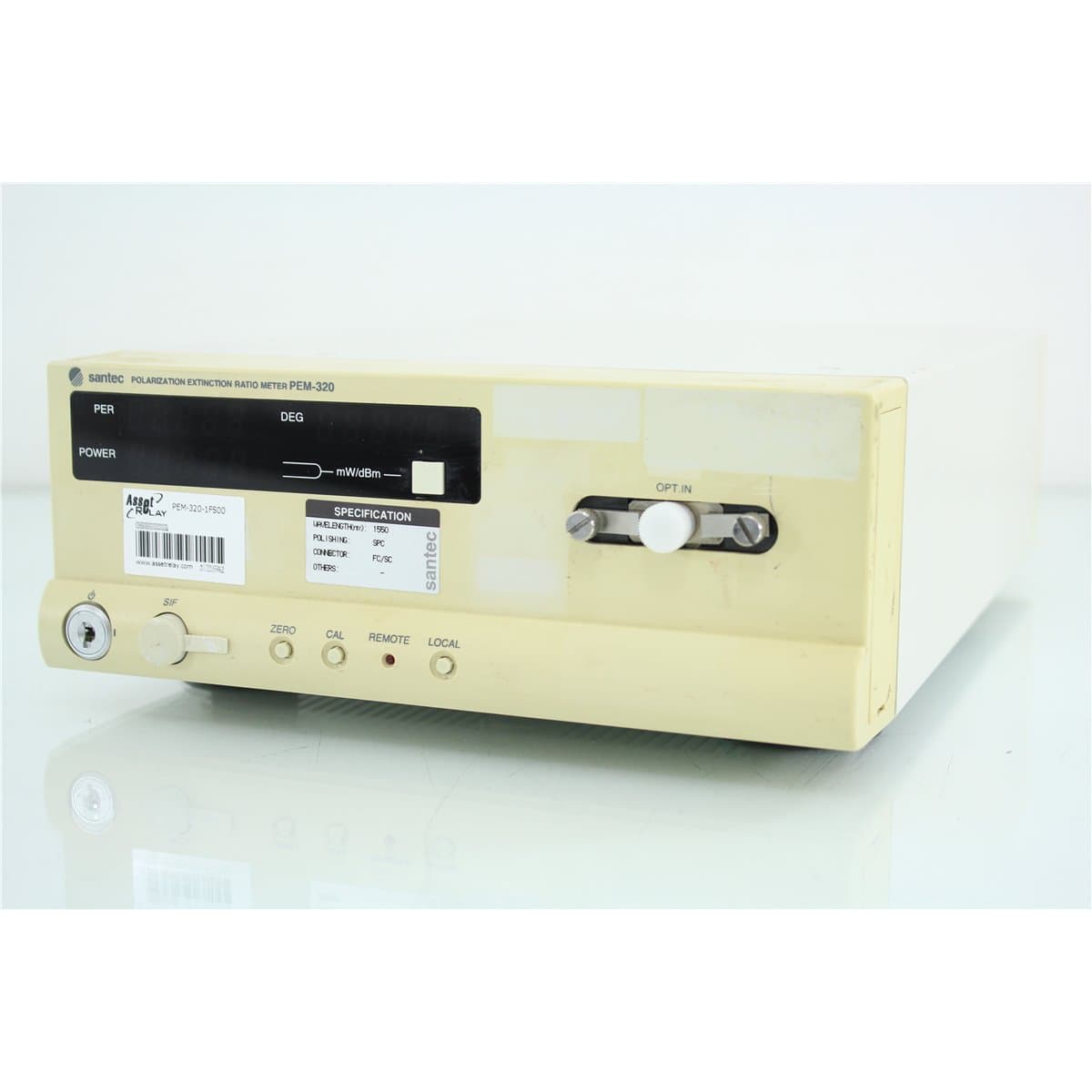
Santec · PEM-320-1FS00
Santec PEM-320 Polarization Extinction Ratio Meter for PM Fiber Alignment
$4,000.00
Price in USD.
- Condition
- Used
- Availability
- In stock · 2 available
- Model
- PEM-320-1FS00
- Manufacturer
- Santec
- Category
- Polarization Extinction Ratio (PER)
Description
Santec PEM-320 Polarization Extinction Ratio Meter
The Santec PEM-320 is a polarization extinction ratio meter designed for fast, accurate alignment of optical components with polarization-maintaining fiber. It provides simultaneous measurement and display of polarization extinction ratio, optical power, and polarization angle, making it suitable for laboratory development, production alignment, component assembly, and quality-control applications.
The instrument measures polarization extinction ratio at two fixed polarization axes, 0° and 90°. Its PER measurement capability extends to 40 dB under the supported input-power conditions, allowing the system to evaluate the alignment quality of compatible polarization-maintaining fiber assemblies and polarization-sensitive optical components.
The PEM-320 supports real-time measurement updates at rates up to 10 Hz. This rapid response allows an operator to observe changes while rotating or positioning the connected fiber, laser diode, optical component, or alignment fixture.
GPIB and RS-232C interfaces support computer control, data acquisition, production-line integration, and automated alignment systems. Compatible utility software is included with the documented instrument configuration for controlling the meter and acquiring or storing measurement data.
Features and Benefits of the Santec PEM-320
- Polarization extinction ratio measurement: Measures PER over a documented range extending to 40 dB under the supported input conditions.
- Simultaneous parameter display: Displays extinction ratio, optical power, and polarization angle together.
- Rapid measurement updates: Supports real-time updates at rates up to 10 Hz for alignment and production testing.
- Fixed-axis measurement: Measures polarization extinction ratio at the 0° and 90° axes.
- Standard input-power range: Measures compatible optical inputs from -30 dBm to +10 dBm.
- Optional high-power input: High-power configurations extend the supported input range from -10 dBm to +20 dBm.
- Multiple wavelength versions: Available for applications near 980, 1310, 1480, and 1550 nm.
- Configurable optical interface: Available with FC/SC, LC/MU, or ST connector interfaces.
- SPC and APC options: Supports model configurations for super physical-contact or angled physical-contact connectors.
- GPIB communication: Enables integration into automated laboratory and production systems.
- RS-232C communication: Supports serial control, data collection, and system integration.
- Optional analog output: A direct photodetector analog output with 1 kHz response supports automated alignment applications.
- Utility software support: Compatible software provides instrument control and measurement-data acquisition or storage.
- Broadband and narrowband measurements: Supports compatible broadband and narrowband optical source testing.
Polarization Extinction Ratio Measurement
Polarization extinction ratio indicates how strongly an optical signal is aligned with one principal polarization axis compared with the orthogonal axis. A higher PER value generally indicates better polarization alignment and lower power in the undesired polarization state.
The PEM-320 measures the optical signal at two fixed axes, 0° and 90°, and calculates the polarization extinction ratio from the measured power relationship. The instrument can also report optical power and polarization angle to assist with alignment and troubleshooting.
The documented PER range is 0 dB to 30 dB when the optical input power is above -30 dBm. Measurements from 30 dB to 40 dB require optical input power above -20 dBm.
PER resolution is 0.1 dB for measurements below 30 dB and 0.3 dB for measurements above 30 dB. Measurement performance depends on the selected wavelength version, connector configuration, source characteristics, input power, fiber condition, and alignment stability.
Optical Power Measurement
The standard PEM-320 input configuration supports optical power measurements from -30 dBm to +10 dBm. An optional high-power version supports inputs from -10 dBm to +20 dBm and incorporates internal attenuation for the higher optical power.
Optical power resolution is 0.1 dB when the measured power is above -30 dBm and 0.3 dB when the measured power is below -30 dBm.
The connected optical source should remain within the input limits of the specific PEM-320 configuration. The standard and high-power versions should not be confused because their allowable power ranges and internal optical arrangements differ.
Polarization Angle Measurement
The PEM-320 measures polarization angle with a documented resolution of 0.45°. This information helps the operator identify the orientation of the optical polarization state relative to the meter’s measurement axes.
Polarization-angle data can support the rotational alignment of laser diodes, polarization-maintaining fibers, pigtails, connectors, and polarization-sensitive components.
For production alignment, the angle reading can be monitored together with PER and optical power to determine whether the component is correctly oriented and whether optical coupling remains stable.
Automated PM Fiber Alignment
The PEM-320 is designed to facilitate the alignment of optical components with polarization-maintaining fiber. During alignment, the fiber or component can be translated and rotated while extinction ratio, optical power, and polarization angle are monitored.
The optional direct photodetector analog output provides a response bandwidth of up to 1 kHz. This signal can be connected to compatible motion-control or automation equipment to support automatic translational alignment based on received optical power.
Rotational alignment can be controlled by monitoring polarization extinction ratio and polarization angle through the instrument’s remote interfaces. The complete automation system may combine the PEM-320 with motorized positioners, rotary stages, motion controllers, laser sources, and custom production software.
GPIB and RS-232C Communication
The PEM-320 includes GPIB and RS-232C communication interfaces for remote control and measurement acquisition. These interfaces allow the meter to be integrated into computer-controlled laboratory and production systems.
Remote operation can support automated configuration, real-time data collection, alignment routines, pass/fail evaluation, and storage of extinction ratio, optical power, and polarization-angle measurements.
Communication cables, computer interfaces, drivers, automation programs, and external controllers should be considered included only when specifically identified in the product listing.
Utility and LabVIEW Software Support
The documented PEM-320 configuration includes utility software for controlling the instrument and acquiring or storing measurement data. LabVIEW software support is also identified for integration into compatible automated test applications.
Software compatibility depends on the operating system, interface hardware, communication settings, software revision, and instrument firmware. Legacy software should be evaluated before the PEM-320 is integrated into a modern computer environment.
Available Wavelength Configurations
The PEM-320 was available in versions optimized for four optical wavelength regions:
- 1550 nm: Suitable for compatible C-band telecommunications and optical amplifier applications.
- 1480 nm: Suitable for compatible optical pump and fiber-amplifier component applications.
- 1310 nm: Suitable for compatible single-mode telecommunications and optical component applications.
- 980 nm: Suitable for compatible pump-laser, amplifier-component, and near-infrared applications.
The installed wavelength version must be confirmed from the complete model number. The general PEM-320 model designation does not identify the optical wavelength range.
Available Connector Configurations
The PEM-320 was offered with FC/SC, LC/MU, or ST connector interfaces. FC/SC configurations could also be supplied with an R-type FC arrangement where applicable.
Connector-polish options include SPC and APC. The connector family and polish must match the connected fiber assembly. APC and non-angled PC or SPC connectors should not be directly intermated.
The complete ordering code should be used to identify the wavelength, connector type, connector polish, power range, and analog-output configuration of an individual instrument.
Typical Applications
- Polarization-maintaining fiber alignment
- Laser diode to PM fiber coupling
- Polarization extinction ratio measurement
- Optical component rotational alignment
- PM fiber pigtail assembly
- Polarization-sensitive component testing
- Broadband optical source measurements
- Narrowband optical source measurements
- Production-line optical alignment
- Automated photonics manufacturing
- Telecommunications laboratory testing
- Photonics research and development
Product Overview
| Brand | Santec |
| Model | PEM-320 |
| Product Series | Polarization Analysis Series |
| Product Category | Polarization Extinction Ratio Meter |
| PER Measurement Range | Up to 40 dB under the supported input conditions |
| Displayed Measurements | Polarization extinction ratio, optical power, and polarization angle |
| Available Wavelength Versions | 980, 1310, 1480, and 1550 nm |
| Standard Input-Power Range | -30 dBm to +10 dBm |
| Optional High-Power Range | -10 dBm to +20 dBm |
| Communication | GPIB and RS-232C |
| Primary Application | Alignment and evaluation of optical components and polarization-maintaining fiber |
Measurement Specifications
| Specification | Details |
| PER Range at Input Power Above -30 dBm | 0 dB to 30 dB |
| PER Range at Input Power Above -20 dBm | 30 dB to 40 dB |
| PER Resolution Below 30 dB | 0.1 dB |
| PER Resolution Above 30 dB | 0.3 dB |
| Standard Optical Power Range | -30 dBm to +10 dBm |
| Optional High-Power Range | -10 dBm to +20 dBm |
| Power Resolution Above -30 dBm | 0.1 dB |
| Power Resolution Below -30 dBm | 0.3 dB |
| Polarization Angle Resolution | 0.45° |
| Measurement Speed | 0.1, 0.2, or 0.4 seconds, selectable |
| Maximum Update Rate | Up to 10 Hz |
Interface and Physical Specifications
| Specification | Details |
| Available Connector Types | FC/SC, LC/MU, or ST |
| Available Connector Polish | SPC or APC |
| Communication Interfaces | GPIB and RS-232C |
| Dimensions | 210 x 80 x 300 mm |
| Weight | Approximately 3 kg |
| AC Input | 100 V to 240 V AC |
| Maximum Power Consumption | 40 W |
| Operating Temperature | 25 °C ±5 °C |
| Compliance | CE marked |
Ordering Code Structure
| Ordering Position | Available Code | Description |
| A: Wavelength Range | 1 | 1550 nm version |
| A: Wavelength Range | 2 | 1480 nm version |
| A: Wavelength Range | 3 | 1310 nm version |
| A: Wavelength Range | 4 | 980 nm version |
| B: Connector Type | F | FC/SC interface |
| B: Connector Type | L | LC/MU interface |
| B: Connector Type | S | ST interface |
| C: Connector Polish | S | SPC |
| C: Connector Polish | A | APC |
| D: Input-Power Version | 0 | Standard -30 dBm to +10 dBm range |
| D: Input-Power Version | H | High-power -10 dBm to +20 dBm range |
| E: Analog Through | 0 | No direct analog output |
| E: Analog Through | T | Direct photodetector analog output |
Configuration Verification
The complete PEM-320 ordering code should be recorded from the physical instrument label before the specification is finalized. The suffix identifies the wavelength, optical connector, ferrule polish, input-power range, and analog-output option.
A standard-power unit should not be exposed to the +20 dBm input level supported by the optional high-power configuration. Likewise, analog alignment output should not be assumed unless the ordering code ends with the T option and the physical output is present.
The installed connector should be inspected before selecting patch cords. FC/SC, LC/MU, and ST interfaces require different connector hardware, while SPC and APC ferrule finishes must be matched correctly.
Comprehensive Functional and Performance Testing
The Santec PEM-320 receives comprehensive functional and performance testing before shipment. Evaluation may include AC power operation, display condition, front-panel controls, measurement-speed selection, optical power response, polarization-angle measurement, PER measurement, and operation at the fixed 0° and 90° axes.
Communication testing may include GPIB and RS-232C operation. Compatible utility or LabVIEW software may be used to confirm remote configuration, real-time measurement acquisition, and data storage.
When the analog-through option is installed, testing may include direct photodetector output, response bandwidth, and suitability for alignment monitoring. Optical testing should use a source and PM fiber configuration matching the installed wavelength and connector options.
The optical input, connector adapter, detector head, controls, display, communication interfaces, analog output when installed, AC inlet, enclosure, labels, and installed options may be inspected for contamination, damage, corrosion, or excessive wear.
The exact testing scope depends on the wavelength version, input-power option, connector type, connector polish, analog-output option, compatible PM source, polarization controller, reference fibers, and available polarization-analysis equipment.
Buyer Considerations
Buyers should confirm the complete PEM-320 ordering code before purchase. The general PEM-320 model alone does not establish the wavelength version, connector type, connector polish, standard or high-power input range, or analog-output option.
The product listing should identify whether optical patch cords, connector adapters, GPIB cable, RS-232C cable, utility software, LabVIEW drivers, power cord, manual, calibration documentation, or automated alignment hardware are included.
Only the Santec PEM-320 meter and accessories specifically identified in the product listing should be considered included.
Why Buy from AssetRelay?
AssetRelay supplies professional equipment and product solutions for fiber optic, telecommunications, optical testing, photonics, laboratory, production, inspection, electronic testing, RF/microwave, and technical research applications. The Santec PEM-320 provides polarization extinction ratio measurement for PM fiber manufacturers, laser diode assemblers, telecommunications laboratories, production facilities, system integrators, universities, and photonics research organizations.
Buyers should review the complete option code, wavelength version, optical connector, ferrule polish, input-power range, analog-output option, PER response, optical power measurement, polarization-angle measurement, communication interfaces, functional test results, and included accessories before purchase.