
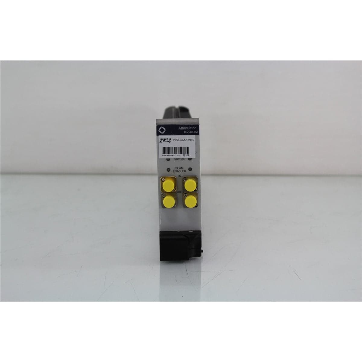
JDS · MVOA-A2DSM-M101
JDSU MAP mVOA-A2 Dual 50/125 µm Multimode Attenuator with Power Monitor
$3,032.00
Price in USD.
- Condition
- Used
- Availability
- In stock
- Model
- MVOA-A2DSM-M101
- Manufacturer
- JDS
- Category
- Optical Attenuators 50-125
Description
JDSU MAP mVOA-A2 Dual 50/125 µm Multimode Attenuator with Power Monitor
The JDSU MAP mVOA-A2 is a dual-channel variable optical attenuator module configured for 50/125 µm multimode fiber and integrated optical power monitoring. Designed for the JDSU MAP-200 Multiple Application Platform, the module provides accurate and repeatable optical signal-level control for laboratory, manufacturing, calibration, and automated fiber optic testing.
Each attenuation channel can be controlled independently through the compatible MAP-200 chassis. The dual-channel design supports simultaneous integration of two optical paths while occupying a compact modular footprint. This configuration is particularly useful for testing dual-channel devices, duplex transceivers, parallel receiver paths, or separate reference and measurement channels.
The multimode mVOA-A2 covers wavelengths from 750 nm to 1350 nm and provides up to 65 dB of attenuation. Attenuation is programmable in 0.001 dB increments with documented accuracy of ±0.1 dB and repeatability of ±0.01 dB under the specified conditions.
An integrated wavelength-calibrated power monitor supports closed-loop optical power control. The module can automatically adjust attenuation to maintain a programmed output level, reducing the number of external optical connections and helping minimize measurement uncertainty in automated test systems.
Features and Benefits of the JDSU MAP mVOA-A2
- Dual independent attenuators: Provides two separately controlled optical attenuation channels in one MAP module.
- 50/125 µm multimode fiber: Supports compatible multimode sources, receivers, transceivers, patch cords, and optical components.
- Integrated power monitoring: Measures optical output power and supports closed-loop power control.
- 750 nm to 1350 nm wavelength range: Covers common multimode test wavelengths, including 850 nm and 1300 nm.
- 65 dB attenuation range: Supports receiver sensitivity testing, loss simulation, and controlled optical-level sweeps.
- 0.001 dB setting resolution: Enables fine programmable adjustment of the optical attenuation.
- ±0.1 dB attenuation accuracy: Supports dependable signal-level control under the documented conditions.
- ±0.01 dB repeatability: Helps recreate optical levels during repeated and automated test sequences.
- Fast attenuation transitions: Provides a typical multimode attenuation slew rate of 20 dB/s.
- Low insertion loss: Provides less than 2.2 dB insertion loss with the integrated power monitor, excluding any applicable tap-coupler loss.
- Closed-loop output control: Supports programmed optical output levels from -40 dBm to +5 dBm near 850 nm and 1310 nm.
- High-isolation shutters: Provides 100 dB typical shutter isolation for optical signal interruption.
- MAP-200 automation: Supports LXI-compliant Ethernet connectivity and compatible IVI drivers through the host platform.
- Hot-pluggable module: Designed for installation in compatible MAP chassis systems.
Dual-Channel Attenuation
The dual mVOA-A2 configuration provides two independently controlled variable optical attenuators. Each channel contains its own optical input, attenuator path, output, and integrated power-monitoring function.
This architecture supports test systems requiring separate optical-level control on two paths. Typical examples include duplex transceiver testing, side-by-side receiver evaluation, dual-source systems, reference and measurement paths, and production fixtures containing two optical channels.
The two channels can be programmed separately through the MAP-200 control system. Each channel can use its own attenuation or closed-loop output-power setting according to the requirements of the test sequence.
50/125 µm Multimode Fiber Configuration
The M101 fiber option identifies 50/125 µm multimode fiber. Compatible multimode patch cords, sources, receivers, detectors, and devices under test should be used throughout the optical path.
Multimode measurements can be affected by source launch conditions, numerical aperture, modal distribution, connector alignment, fiber bends, patch-cord routing, and detector geometry. Reference cables and launch conditions should remain consistent when comparative or calibrated measurements are performed.
Single-mode and 62.5/125 µm multimode patch cords should not be substituted when the test procedure requires controlled 50/125 µm operation.
Integrated Optical Power Monitor
The integrated optical power monitor measures the output signal within each attenuation channel. This reduces the need for an external optical tap, additional patch cord, and separate power meter in applications requiring output-level monitoring.
The documented closed-loop output range is -40 dBm to +5 dBm near 850 nm and 1310 nm. Relative power meter uncertainty is ±0.03 dB under the specified conditions.
Power-setting repeatability is ±0.015 dB, and programmed power setting resolution is 0.001 dBm. These capabilities support automated receiver sensitivity tests and procedures requiring repeatable optical power at the device under test.
Closed-Loop Optical Power Control
In closed-loop operation, the mVOA-A2 uses its internal power monitor to measure the output and adjust attenuation until the programmed optical power is reached. This helps compensate for supported source-level changes and other variations upstream of the attenuator.
Closed-loop control can improve measurement repeatability in automated laboratory and production systems. It can also simplify setup by combining attenuation and power monitoring within the same module.
The wavelength setting should match the optical source because detector responsivity changes with wavelength. The documented closed-loop specifications apply near 850 nm and 1310 nm within the specified wavelength tolerances.
65 dB Multimode Attenuation Range
The multimode mVOA-A2 provides an attenuation range of 65 dB. This allows the module to make small optical-level corrections or reduce a signal substantially for receiver sensitivity and low-power testing.
The programmed attenuation should remain within the supported range and the optical input should remain below the module’s maximum input-power rating. The final output level also depends on insertion loss, patch cords, connectors, and other components in the optical path.
An external calibrated power meter should be used when independent verification of the delivered optical power is required.
Attenuation Accuracy and Repeatability
Attenuation accuracy is specified at ±0.1 dB under the documented conditions. Attenuation repeatability is ±0.01 dB at constant wavelength, temperature, and state of polarization.
The specified multimode attenuation performance applies near 850 nm and 1300 nm and across attenuation settings from 0 dB to 45 dB under the documented test conditions.
Total measurement uncertainty also depends on source stability, wavelength accuracy, launch conditions, connector cleanliness, fiber routing, external optical loss, detector response, and the calibration status of the test system.
Fast Attenuation Transitions
The multimode mVOA-A2 provides a typical attenuation slew rate of 20 dB/s. Fast attenuation changes help reduce test time when a measurement sequence requires several optical power points.
The stepper-motor and optical-filter design supports programmable attenuation sweeps and repeatable transitions between test levels. Complete test speed also depends on power-monitor averaging, device response, communication latency, and automation software.
Low Insertion Loss
The multimode module with integrated power control provides insertion loss below 2.2 dB under the documented conditions. If a tap coupler is included in the optical configuration, approximately 0.7 dB of additional coupler loss should be considered where applicable.
Low insertion loss helps preserve the available optical power and test-system dynamic range. External connectors, patch cords, switches, adapters, and devices under test contribute additional optical loss.
Optical Shutter
Each compatible attenuation path includes an optical shutter with 100 dB typical isolation. The shutter can interrupt the optical output without switching off the source or changing the programmed attenuation value.
This function supports dark measurements, receiver protection, automated signal-on and signal-off testing, system reconfiguration, and controlled test sequencing.
The shutter should not replace established fiber optic safety procedures. Optical sources should still be disabled before connectors are inspected, cleaned, installed, or removed.
MAP-200 Automation
The mVOA-A2 is optimized for the JDSU MAP-200 modular photonic test platform. MAP-200 systems support LXI-compliant physical interfaces, Ethernet connectivity, and compatible IVI drivers.
Automated operation allows a controlling computer to set attenuation, program output power, activate the shutter, monitor status, collect results, and coordinate the module with other optical and electronic test equipment.
A compatible MAP chassis, controller, firmware, drivers, and software are required. These components should be considered included only when specifically identified in the product listing.
Typical Applications
- Multimode receiver sensitivity testing
- Dual-channel transceiver evaluation
- Optical loss simulation
- Transmitter dispersion testing
- Eye-mask testing
- Optical power meter calibration
- 50/125 µm multimode component characterization
- Automated optical-level sweeps
- Optical detector testing
- Laboratory test-system integration
- Manufacturing and production testing
- Telecommunications research and development
Product Overview
| Brand | JDSU |
| Product Family | MAP mVOA-A2 |
| Product Category | Dual Variable Optical Attenuator with Power Monitoring |
| Attenuator Channels | Two independent channels |
| Fiber Type | 50/125 µm multimode fiber |
| Wavelength Range | 750 nm to 1350 nm |
| Attenuation Range | 65 dB |
| Integrated Measurement | Wavelength-calibrated optical power monitor on each channel |
| Compatible Platform | JDSU MAP-200 Multiple Application Platform |
| Standalone Operation | Not supported |
| Primary Application | Automated dual-channel multimode attenuation and output-power control |
Multimode Optical Specifications
| Specification | Details |
| Fiber Configuration | 50/125 µm multimode fiber |
| Wavelength Range | 750 nm to 1350 nm |
| Attenuation Range | 65 dB |
| Attenuation Setting Resolution | 0.001 dB |
| Attenuation Accuracy | ±0.1 dB under the documented conditions |
| Attenuation Repeatability | ±0.01 dB |
| Typical Attenuation Slew Rate | 20 dB/s |
| Insertion Loss with Power Control | Less than 2.2 dB, excluding any applicable tap-coupler loss |
| Maximum Standard Input Power | +23 dBm |
| Maximum High-Power Option Input | +27 dBm, equivalent to approximately 500 mW |
| Typical Return Loss | Greater than 30 dB with a PC connector |
| Typical Shutter Isolation | 100 dB |
Integrated Power Monitor Specifications
| Specification | Details |
| Closed-Loop Output Range | -40 dBm to +5 dBm near 850 nm and 1310 nm |
| Relative Power Meter Uncertainty | ±0.03 dB |
| Power-Setting Repeatability | ±0.015 dB |
| Power-Setting Resolution | 0.001 dBm |
| Documented Multimode Calibration Wavelengths | 850 nm and 1310 nm, each within ±15 nm |
Physical and Environmental Specifications
| Specification | Details |
| Module Width | 4.06 cm, or 1.6 in |
| Module Height | 13.26 cm, or 5.22 in |
| Module Depth | 37.03 cm, or 14.58 in |
| Dual-Channel Module Weight | Approximately 1.3 kg, or 2.87 lb |
| Warm-Up Time | 30 minutes |
| Calibration Period | Two years |
| Operating Temperature | 0 °C to 50 °C |
| Storage Temperature | -30 °C to 60 °C |
| Operating Humidity | Less than 90% at 23 °C and less than 20% at 50 °C, non-condensing |
Ordering Configuration
| Configuration Element | Required Option |
| Base Configuration | MVOA-A2DSM for dual attenuators, standard power, and integrated power monitors, or MVOA-A2DHM for the corresponding high-power version |
| Fiber Option | M101 for 50/125 µm multimode fiber |
| Connector Option | Confirm MFP for FC/PC, MFA for FC/APC, MSC for SC/PC, or MSU for SC/APC |
Configuration Details Requiring Verification
| Configuration Item | Verification Required |
| Complete Model Number | Confirm the full mVOA-A2 base, fiber, and connector option code |
| Power Version | Confirm standard-power or high-power configuration |
| Connector Type | Confirm FC/PC, FC/APC, SC/PC, or SC/APC |
| Channel Count | Confirm that both attenuator and power-monitor channels are recognized by the MAP chassis |
| Host Compatibility | Confirm operation with the available MAP-200 chassis, controller, firmware, and software |
Installation and System Integration
The mVOA-A2 should be installed in a compatible JDSU MAP-200 chassis. The module should be seated securely and recognized by the host platform before optical connections are made.
Compatible 50/125 µm multimode patch cords should be connected to each channel’s input and output. The connector family and ferrule polish must match the installed module configuration.
For high-power applications, optical power must travel from the designated IN port toward the OUT port. Scratched or contaminated connectors can be damaged at high optical power and may also damage the module interface.
When connecting a sensitive receiver, the module should initially be set to a high attenuation value or closed-loop low-power setting. The optical level can then be increased gradually while the receiving device is monitored.
Connector Inspection and Cleaning
Every optical port and mating patch cord should be inspected before connection. Contaminated connectors should be cleaned using an approved fiber optic procedure and reinspected before mating.
Clean optical interfaces help preserve insertion loss, repeatability, optical power accuracy, return loss, and connector condition. Connector cleanliness is particularly important when operating near the high-power input limits.
Protective caps should remain installed on unused optical ports. Caps should also be kept clean to prevent contamination from being transferred to the module.
Comprehensive Functional and Performance Testing
The JDSU MAP mVOA-A2 dual multimode attenuator receives comprehensive functional and performance testing before shipment. Evaluation may include installation in a compatible MAP chassis, module recognition, startup, independent control of both channels, attenuation programming, shutter operation, and power-monitor response.
Optical testing may include input-to-output continuity, insertion loss, representative attenuation points, attenuation repeatability, closed-loop output power, power-monitor response, and shutter isolation on both channels using compatible calibrated multimode equipment.
The optical ports, module faceplate, controls, chassis connector, enclosure, labels, and installed option markings may be inspected for contamination, damage, corrosion, fiber stress, or excessive wear.
The exact testing scope depends on the full model number, power version, connector type, compatible chassis, available 50/125 µm sources, reference patch cords, calibrated optical power meters, and requested wavelengths and power levels.
Calibration Before Shipment
When technically applicable and selected, the JDSU MAP mVOA-A2 can be calibrated or performance-verified before shipment. Evaluation may include insertion loss, attenuation accuracy, repeatability, power-monitor accuracy, closed-loop power settings, wavelength response, and shutter isolation for both channels.
Calibration documentation should identify the module model and serial number, channel, fiber type, optical connectors, host chassis, test wavelength, attenuation settings, input and output power, reference patch cords, measurement equipment, recorded results, and applicable measurement uncertainty.
Buyers requiring formal calibration should specify the required channels, wavelengths, attenuation points, optical power levels, connector configuration, certificate format, recorded data, and required measurement uncertainty before purchase.
Buyer Considerations
Buyers should confirm the complete product code. A dual 50/125 µm module with integrated power monitors should use the MVOA-A2DSM or MVOA-A2DHM base configuration together with the M101 fiber option and the applicable connector code.
The product listing should identify whether the module is standard power or high power and whether the optical connectors are FC/PC, FC/APC, SC/PC, or SC/APC.
The compatible MAP chassis, controller, software, documentation, optical patch cords, protective caps, communication cables, test records, and calibration certificate should be considered included only when specifically identified in the product listing.
Only the JDSU mVOA-A2 module and accessories specifically identified in the product listing should be considered included.
Why Buy from AssetRelay?
AssetRelay supplies professional equipment and product solutions for fiber optic, telecommunications, optical testing, photonics, laboratory, production, inspection, electronic testing, RF/microwave, and technical research applications. The JDSU MAP mVOA-A2 provides dual-channel attenuation and power monitoring for transceiver manufacturers, receiver developers, telecommunications laboratories, production facilities, system integrators, universities, and research organizations.
Buyers should review the complete model code, dual-channel configuration, 50/125 µm fiber, integrated power monitors, wavelength and attenuation ranges, connector type, power version, MAP-200 compatibility, functional test results, calibration status, and included accessories before purchase.