
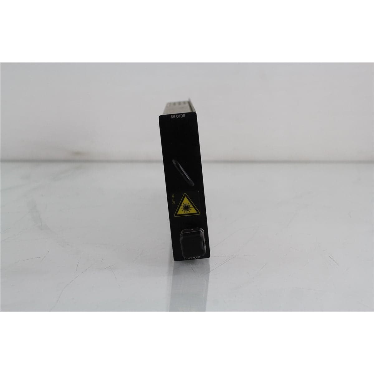
Exfo · FTB-7434B-B-EI
EXFO FTB-7434B-EI 1550/1625 nm Single-Mode OTDR Module
$3,192.00
Price in USD.
- Condition
- Used
- Availability
- In stock
- Model
- FTB-7434B-B-EI
- Manufacturer
- Exfo
- Category
- OTDRs
Description
EXFO FTB-7434B-EI 1550/1625 nm Single-Mode OTDR Module
The EXFO FTB-7434B-EI is a dual-wavelength optical time domain reflectometer module designed for testing single-mode fiber at 1550 nm and 1625 nm. It provides fiber characterization, event location, loss analysis, and troubleshooting capabilities for telecommunications, outside-plant, metropolitan, access, and long-haul optical networks.
The module combines a standard 1550 nm transmission wavelength with a maintenance-oriented 1625 nm wavelength. This dual-wavelength configuration helps technicians evaluate normal link performance while also identifying wavelength-sensitive losses, including bends and stressed fiber sections that may be more visible at 1625 nm.
When installed in a compatible EXFO FTB modular test platform, the FTB-7434B-EI can help locate fiber breaks, connectors, fusion splices, mechanical splices, reflective events, bends, and other changes in the optical path. The host platform provides the display, processing, controls, data storage, software, and reporting functions required for field and laboratory measurements.
Features and Benefits of the EXFO FTB-7434B-EI
- Dual-wavelength testing: Combines 1550 nm and 1625 nm single-mode OTDR measurements in one modular instrument.
- Transmission-band analysis: Uses the 1550 nm wavelength for testing common single-mode telecommunications links.
- Maintenance wavelength: Uses 1625 nm to support troubleshooting and detection of wavelength-sensitive fiber losses.
- Fiber event location: Helps locate connectors, splices, breaks, reflective faults, bends, and other events along an optical link.
- Loss measurement: Supports evaluation of event loss, fiber attenuation, link length, and total optical path loss.
- Long-range capability: The FTB-7434B family provides high dynamic range for analyzing long or lossy single-mode fiber links.
- Short event dead zone: Provides a typical 3 m event dead zone at both supported wavelengths under the documented conditions.
- Dual-trace comparison: Allows 1550 nm and 1625 nm results to be compared when evaluating bends and other wavelength-dependent events.
- Modular EXFO format: Installs in a compatible EXFO FTB test platform for portable or system-based measurements.
- Professional field applications: Supports installation, commissioning, acceptance testing, maintenance, restoration, and troubleshooting workflows.
1550 nm Single-Mode OTDR Testing
The 1550 nm channel is intended for single-mode fiber characterization in a commonly used telecommunications transmission window. It can be used to measure fiber length, locate events, evaluate splice and connector loss, and review the attenuation of an installed link.
Because standard single-mode fiber generally exhibits lower attenuation at 1550 nm than at 1310 nm, this wavelength is useful for testing long links and systems with substantial cumulative loss. It is suitable for outside-plant networks, metropolitan infrastructure, long-haul routes, access systems, and laboratory fiber spools.
A suitable launch fiber can be used to move the first network connection beyond the OTDR dead zone and support measurement of the near-end connector. A receive fiber can be added when the far-end connector and complete end-to-end loss must also be evaluated.
1625 nm Maintenance Testing
The 1625 nm wavelength is commonly used for maintenance, monitoring, and troubleshooting of single-mode fiber infrastructure. It can help reveal wavelength-sensitive attenuation that may be less apparent at lower test wavelengths.
Bends, compression points, and stressed fiber sections may produce greater loss at 1625 nm than at 1550 nm. Comparing traces acquired at both wavelengths can help distinguish bend-related events from ordinary splices or connectors.
The 1625 nm test path should only be connected to equipment and networks designed to accommodate the wavelength and applied test signal. Suitable wavelength-selective filters or maintenance access equipment may be required when testing fiber associated with an active optical system.
High-Dynamic-Range Fiber Analysis
The FTB-7434B family is intended for demanding single-mode measurements requiring high dynamic range. High dynamic range helps the OTDR analyze long fiber spans and links containing multiple connectors, splices, or other loss-producing events.
The available dynamic range depends on the exact module configuration. Published FTB-7434B configurations include models with different performance levels, identified by ER1 and ER2 suffixes. The complete model and configuration shown on the individual module label should therefore be verified before assigning exact dynamic-range values to an EI-designated unit.
Actual measurable distance also depends on pulse width, averaging time, wavelength, fiber attenuation, event loss, connector condition, noise level, and the required signal-to-noise ratio.
Event and Attenuation Dead Zones
The FTB-7434B family provides a typical event dead zone of 3 m at both 1550 nm and 1625 nm under the documented single-mode test conditions. The typical attenuation dead zone is 15 m at 1550 nm and 20 m at 1625 nm.
The event dead zone describes the minimum separation required to distinguish events following a reflective event under specified conditions. The attenuation dead zone describes the distance required for the trace to return sufficiently close to the backscatter level for accurate loss analysis.
Launch and receive fibers remain important when the first connector, final connector, or closely spaced near-end events must be characterized accurately.
Automatic and Manual OTDR Analysis
When used with compatible EXFO platform software, the module can support automatic trace acquisition and event analysis. Automatic functions help technicians identify events and organize measurement results into an event table.
Manual marker functions can be used to study selected portions of a trace, measure distance between points, evaluate section attenuation, and review unusual events that require additional interpretation.
Automatic analysis should be reviewed together with the displayed waveform. Low-loss splices, closely spaced events, complex splitter networks, unusual reflections, and noisy fiber ends may require manual confirmation.
Typical Applications
- 1550 nm single-mode fiber characterization
- 1625 nm maintenance and troubleshooting measurements
- Long-haul and metropolitan fiber testing
- Outside-plant installation and acceptance testing
- Fiber break and fault location
- Splice-loss and connector-loss analysis
- Macrobend and stressed-fiber detection
- Fiber length and attenuation measurement
- Network restoration and preventive maintenance
- Telecommunications access-network testing
- Fiber baseline documentation
- Laboratory and production fiber analysis
Product Overview
| Brand | EXFO |
| Model | FTB-7434B-EI |
| Product Category | Dual-Wavelength Single-Mode OTDR Module |
| Measurement Wavelengths | 1550 nm and 1625 nm |
| Applicable Fiber | Single-mode optical fiber |
| Module Format | EXFO FTB platform module |
| Primary Application | Single-mode fiber characterization, maintenance, fault location, and loss analysis |
Supported Optical Specifications
| Specification | Details |
| First OTDR Wavelength | 1550 nm ±20 nm |
| Second OTDR Wavelength | 1625 nm ±10 nm |
| Typical Event Dead Zone at 1550 nm | 3 m |
| Typical Event Dead Zone at 1625 nm | 3 m |
| Typical Attenuation Dead Zone at 1550 nm | 15 m |
| Typical Attenuation Dead Zone at 1625 nm | 20 m |
| Documented Test Condition | 23 °C with an FC/UPC single-mode connector unless otherwise specified |
FTB-7434B Family Configurations
| Documented Model | Wavelengths | Typical Dynamic Range at 10 µs | Typical Dynamic Range at 20 µs |
| FTB-7434B-ER1 | 1550 nm / 1625 nm | 37 dB / 36 dB | 38.5 dB / 37.5 dB |
| FTB-7434B-ER2 | 1550 nm / 1625 nm | 40 dB / 39 dB | 41.5 dB / 40.5 dB |
Configuration Identification
The supplied model is identified as FTB-7434B-EI. The available specification material documents FTB-7434B-ER1 and FTB-7434B-ER2 configurations but does not define an EI suffix.
The module identification label, installed platform software, product photographs, and system information should be reviewed to determine whether EI is the exact factory designation, an inventory identifier, or a reading of an ER1 suffix.
Exact dynamic range should not be assigned until the suffix is verified. If the unit is confirmed as ER1, its published typical dynamic range is 37 dB at 1550 nm and 36 dB at 1625 nm using a 10 µs pulse. If confirmed as ER2, the corresponding values are 40 dB and 39 dB.
Connection and Measurement Considerations
The installed optical connector should be identified before selecting launch cables, receive cables, and patch cords. The available specifications use an FC/UPC single-mode connector as the reference configuration unless otherwise stated.
All optical interfaces should be inspected and cleaned before connection. Contamination can reduce launch power, increase reflections, create false events, alter dead-zone performance, and damage the module or mating cable.
The connector type and polish must match the attached test cable. Angled-polish and straight-polish interfaces should not be directly intermated unless the complete connection is specifically designed for that combination.
The correct index of refraction should be entered before relying on absolute distance results. Pulse width, averaging time, distance range, and analysis thresholds should be selected according to the link length, cumulative loss, event spacing, and required resolution.
Comprehensive Functional and Performance Testing
The EXFO FTB-7434B-EI receives comprehensive functional and performance testing before shipment. Testing may include installation in a compatible FTB platform, module recognition, software communication, 1550 nm and 1625 nm wavelength selection, optical output activation, trace acquisition, event detection, marker functions, and data storage.
Optical testing may include representative measurements on suitable single-mode reference fibers, event-location verification, relative-loss response, dead-zone evaluation, and trace stability. The exact performance limits applied during testing depend on confirmation of the module suffix and configuration.
The optical port may also be inspected for contamination, damaged threads, worn alignment components, loose adapters, or other conditions that could affect launch power and measurement quality.
The exact testing scope depends on the verified module configuration, installed connector, compatible FTB platform, available single-mode reference fibers, launch cables, reflectors, attenuators, optical power meters, and supporting calibration equipment.
Calibration Before Shipment
When technically applicable and selected, the EXFO FTB-7434B-EI can be calibrated or performance-verified before shipment. Calibration may include optical output wavelength, distance accuracy, loss linearity, event dead zone, attenuation dead zone, dynamic range, and optical connector condition.
Calibration should be completed using suitable single-mode reference fibers, traceable length standards, calibrated attenuation standards, reference reflectors, and compatible optical measurement equipment.
Buyers requiring formal calibration should confirm the exact module suffix, requested wavelengths, test points, connector configuration, certificate type, recorded data, and measurement uncertainty before purchase.
Buyer Considerations
Buyers should verify the complete model number printed on the module. The distinction between FTB-7434B-EI, FTB-7434B-ER1, and FTB-7434B-ER2 is important because the documented ER1 and ER2 versions have different dynamic-range specifications.
The listing should identify whether the sale includes the OTDR module only or a compatible EXFO FTB platform. Launch fibers, receive fibers, connector adapters, batteries, power supplies, software, manuals, carrying cases, and calibration records may be required separately.
The optical connector, module guides, retaining hardware, enclosure, labels, and host-platform interface should be reviewed for damage or excessive wear.
Only the OTDR module, FTB platform, optical adapters, launch and receive fibers, batteries, power accessories, carrying case, software, documentation, calibration records, and accessories specifically identified in the product listing should be considered included.
Why Buy from AssetRelay?
AssetRelay supplies professional equipment and product solutions for fiber optic, telecom, laboratory, production, optical test, inspection, cleaning, electronic test, RF/microwave, and photonics applications. The EXFO FTB-7434B-EI supports field technicians, network operators, laboratories, service organizations, system integrators, and technical procurement teams requiring 1550 nm and 1625 nm single-mode OTDR testing.
Buyers should review the product photographs, exact model suffix, connector configuration, wavelength operation, dynamic-range configuration, compatible platform requirements, calibration status, functional test results, and included accessories before purchase.