
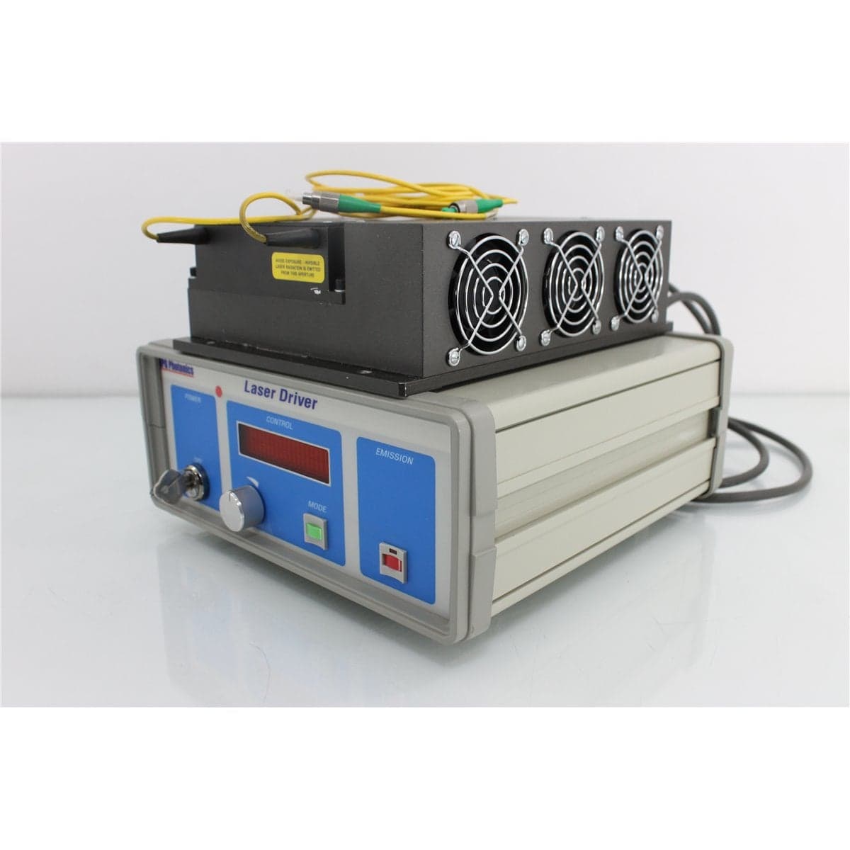
IPG-Polus · EAU-1-L_ASSY
IPG Photonics EAU-1-L 26 dBm L-Band Erbium-Doped Fiber Amplifier
$2,395.20
Price in USD.
- Condition
- Used
- Availability
- In stock
- Model
- EAU-1-L_ASSY
- Manufacturer
- IPG-Polus
- Category
- L-Band EDFAs
Description
IPG Photonics EAU-1-L 26 dBm L-Band Erbium-Doped Fiber Amplifier
The IPG Photonics EAU-1-L is an erbium-doped fiber amplifier designed for high-power optical amplification in L-band fiber optic systems. Its optimized spectral range extends from 1570 nm to 1605 nm, supporting compatible telecommunications, analog optical transmission, laboratory research, production testing, and photonics applications operating beyond the conventional C-band.
The amplifier supports optical input power from -3 dBm to +10 dBm and provides adjustable output from 10 dBm to 26 dBm. The maximum documented output of 26 dBm is equivalent to approximately 398 mW, providing substantial power for compatible optical transmission paths, component test systems, and laboratory experiments.
The EAU-1-L uses SM9/125-3.0 single-mode fiber and FC/APC optical connectors. These angled physical-contact interfaces help reduce reflected optical power when properly connected to clean, compatible FC/APC patch cords. Minimum return loss is specified at 40 dB for both the optical input and output.
The amplifier operates from universal 100-240 VAC power at 50 or 60 Hz and supports operating temperatures from 0 °C to +65 °C. This combination supports integration into laboratory benches, production systems, telecommunications equipment, and technical research environments.
Features and Benefits of the IPG Photonics EAU-1-L
The IPG Photonics EAU-1-L provides controlled L-band optical amplification for professional users working with single-mode fiber systems.
- Optimized L-band coverage: Supports compatible optical signals from 1570 nm to 1605 nm.
- Adjustable optical output: Provides documented output power from 10 dBm to 26 dBm.
- High maximum power: Delivers up to approximately 398 mW at the 26 dBm maximum setting.
- Broad input range: Accepts optical input power from -3 dBm to +10 dBm.
- EDFA architecture: Amplifies compatible optical signals directly within the fiber path.
- FC/APC interfaces: Supports secure, low-reflection optical connections with compatible patch cords.
- Single-mode fiber: Uses SM9/125-3.0 fiber for compatible telecommunications and photonics systems.
- Minimum 40 dB return loss: Applies to both the optical input and output.
- Analog transmission specifications: Includes documented composite second-order and composite triple-beat performance.
- Universal AC input: Operates from 100 VAC to 240 VAC at 50 or 60 Hz.
- Wide operating-temperature range: Supports operation from 0 °C to +65 °C.
1570 nm to 1605 nm Optimized Spectral Range
The EAU-1-L is optimized for compatible optical signals from 1570 nm to 1605 nm. This wavelength range covers a substantial portion of the L-band used in optical communications, wavelength-division multiplexing, amplifier research, and long-wavelength component testing.
L-band amplification extends optical test and transmission capability beyond the conventional C-band. Compatible applications can include L-band filters, multiplexers, demultiplexers, optical switches, attenuators, receivers, detectors, and fiber transmission systems.
Every component in the optical path should support the selected wavelength. This includes patch cords, connector adapters, optical power meters, spectrum analyzers, variable attenuators, switches, and devices under test.
10 dBm to 26 dBm Optical Output
The amplifier provides documented optical output from 10 dBm to 26 dBm. The lower output level of 10 dBm corresponds to 10 mW, while the maximum output of 26 dBm corresponds to approximately 398 mW.
This broad output range allows the amplified signal to be selected according to the requirements of the connected optical system. Lower output settings support initial setup and sensitive receiver testing, while higher settings can compensate for loss introduced by switches, filters, couplers, attenuators, patch cords, and other components.
The supplied specifications state that the output range is measured at 1550 nm with a 0 dBm optical input. Because 1550 nm is outside the stated optimized range of 1570 nm to 1605 nm, output performance at a specific L-band wavelength should be verified directly when wavelength-specific results are required.
A calibrated optical power meter rated for the expected level should be used to confirm the output. External attenuation may be required before connecting the amplifier to sensitive detectors, receivers, optical spectrum analyzers, or standard optical power meters.
-3 dBm to +10 dBm Optical Input Range
The supported optical input range extends from -3 dBm to +10 dBm. This corresponds to approximately 0.5 mW to 10 mW of input power.
The input signal should remain within this range and within the amplifier’s optimized wavelength band. Input power outside the documented limits may prevent the amplifier from producing its expected output or maintaining supported performance.
When the source level is unknown, the signal should be measured before it is connected to the amplifier. A compatible variable optical attenuator can be used to establish a controlled input level.
Erbium-Doped Fiber Amplification
The EAU-1-L increases optical signal power using erbium-doped fiber amplifier technology. Optical pump energy excites erbium ions within the gain fiber, allowing compatible input signals to be amplified as they pass through the instrument.
This process keeps the signal in the optical domain without requiring optical-to-electrical conversion. The amplifier is therefore suitable for compatible fiber transmission experiments, optical component characterization, receiver testing, and wavelength-division multiplexing systems.
Amplifier performance can vary with wavelength, input power, output setting, channel loading, connector reflections, environmental temperature, and operating conditions.
Noise Figure
The documented noise figure is 7.5 dB at 1550 nm with a 0 dBm input. Noise figure describes the degradation in optical signal-to-noise performance introduced by the amplifier.
Amplified spontaneous emission contributes to the output noise floor and can influence signal quality, particularly when relatively weak optical signals are amplified. Noise performance can be evaluated with a compatible optical spectrum analyzer or optical amplifier test system.
The documented noise-figure condition is specified at 1550 nm, while the amplifier is identified as optimized from 1570 nm to 1605 nm. A direct L-band measurement is recommended when noise figure at a particular operating wavelength is important.
Input and Output Return Loss
Input and output return loss is specified at a minimum of 40 dB. Return loss indicates how effectively the optical interfaces limit reflected power returning toward the source or amplifier.
The FC/APC connectors support low-reflection fiber connections when correctly mated with clean FC/APC patch cords. FC/PC and FC/APC connectors must not be directly intermated because their ferrule geometries are incompatible.
Overall system return loss also depends on patch cords, adapters, splices, filters, switches, attenuators, and connected devices. Every optical interface should be inspected and cleaned before connection.
Analog Transmission Performance
The EAU-1-L includes documented performance parameters relevant to compatible analog optical transmission systems. Composite second-order distortion is specified at -75 dBc, while composite triple beat is specified at -80 dBc.
Composite second-order and composite triple-beat specifications describe nonlinear distortion terms that can affect multi-carrier analog transmission. Lower distortion products help reduce interference among supported analog channels.
The complete measurement conditions, including channel loading, wavelength, modulation format, bandwidth, input level, and output setting, are not included in the supplied specifications. These conditions should be verified before the values are applied to a specific system design or acceptance test.
Carrier-to-Noise Ratio and Residual Pump Power
The supplied specifications list a carrier-to-noise ratio greater than 1 dB. Because the associated bandwidth, channel loading, measurement method, and operating conditions are not provided, this value should be confirmed directly before use in an analog system calculation.
Residual pump power is specified at -20 dBm/nm. Residual pump energy can be relevant when the amplifier output is connected to wavelength-sensitive detectors, receivers, filters, or optical spectrum analyzers.
A suitable wavelength-selective filter may be used when additional rejection of residual pump energy is required. The amplifier output spectrum should be measured directly when amplified spontaneous emission, residual pump content, or out-of-band optical energy is important.
Single-Mode Fiber and FC/APC Connectors
The amplifier uses SM9/125-3.0 single-mode fiber for its optical input and output. Compatible single-mode patch cords and components should be used throughout the optical path.
The FC/APC connectors use angled ferrules to reduce reflected optical power. Their threaded coupling mechanism provides a secure connection for laboratory, rack-mounted, and production applications.
Patch cords should be routed with an appropriate bend radius and protected from crushing, pulling, twisting, and excessive mechanical stress. Fiber movement and tight bends can affect delivered optical power and measurement stability.
Typical Applications
The IPG Photonics EAU-1-L is suitable for professional applications such as:
- L-band optical signal amplification
- 1570 nm to 1605 nm component testing
- Wavelength-division multiplexing experiments
- Optical transmission-system development
- Receiver and detector evaluation
- Optical filter and multiplexer testing
- Fiber switch and attenuator characterization
- Analog fiber transmission experiments
- Optical spectrum analysis
- Laboratory photonics research
- Production and quality-control testing
- High-power L-band test systems
Product Overview
| Brand | IPG Photonics |
| Model | EAU-1-L |
| Product Category | L-Band Erbium-Doped Fiber Amplifier |
| Optimized Spectral Range | 1570 nm to 1605 nm |
| Optical Output Range | 10 dBm to 26 dBm |
| Optical Input Range | -3 dBm to +10 dBm |
| Connector Type | FC/APC |
| Fiber Type | SM9/125-3.0 single-mode fiber |
| Primary Application | Controlled amplification of compatible L-band optical signals |
Optical Specifications
| Specification | Details |
| Optimized Spectral Range | 1570 nm to 1605 nm |
| Optical Output Power | 10 dBm to 26 dBm at 1550 nm with a 0 dBm input |
| Maximum Optical Output | Approximately 398 mW at 26 dBm |
| Optical Input Power Range | -3 dBm to +10 dBm |
| Input Range in Milliwatts | Approximately 0.5 mW to 10 mW |
| Noise Figure | 7.5 dB at 1550 nm with a 0 dBm input |
| Input Return Loss | 40 dB minimum |
| Output Return Loss | 40 dB minimum |
| Carrier-to-Noise Ratio | Greater than 1 dB under the supplied specification conditions |
| Composite Second Order | -75 dBc |
| Composite Triple Beat | -80 dBc |
| Residual Pump Power | -20 dBm/nm |
Electrical, Fiber, and Environmental Specifications
| Specification | Details |
| AC Input | 100 VAC to 240 VAC |
| Line Frequency | 50 Hz or 60 Hz |
| Operating Temperature | 0 °C to +65 °C |
| Optical Connector | FC/APC |
| Fiber Type | Single-mode SM9/125-3.0 |
Installation and Optical Setup
The IPG Photonics EAU-1-L should be installed on a stable laboratory bench or in a suitable equipment rack with sufficient clearance for ventilation, optical patch cords, AC power, and operator access.
The optical input and output should be identified before patch cords are connected. The optical source connects to the amplifier input, while the device under test, attenuator, power meter, spectrum analyzer, or transmission path connects to the amplifier output.
All FC/APC connectors should be inspected and cleaned before mating. Compatible single-mode patch cords should be routed with an appropriate bend radius and strain relief.
The amplifier should initially be operated at its lowest practical output setting. A calibrated high-power optical meter, beam tap, or appropriate external attenuator should be used to verify output before sensitive equipment is connected.
Connector Care and Maintenance
The FC/APC input and output connectors should remain protected from dust, oil, moisture, scratches, and physical damage. Contamination can increase insertion loss, reduce return loss, destabilize operation, and damage mating connector end faces.
Approved fiber inspection and cleaning equipment should be used before every connection. The connector should be reinspected after cleaning and before mating.
Clean protective caps should remain installed whenever the input or output is not in use. Dirty or damaged caps should not be returned to cleaned connectors.
Optical Safety
The EAU-1-L can produce up to approximately 398 mW of invisible infrared optical power. The absence of visible light does not indicate that the amplifier output is disabled.
Users should not look into the FC/APC output, patch cord, adapter, or exposed fiber end. The amplifier and connected source should be disabled before optical interfaces are inspected, cleaned, attached, or removed.
Suitable laser-safety procedures, protective equipment, shielding, warning labels, interlocks, and controlled work practices should be used according to the measured output level and complete optical setup.
Comprehensive Functional and Performance Testing
The IPG Photonics EAU-1-L receives comprehensive functional and performance testing before shipment. Evaluation may include AC power operation, startup, front-panel controls, optical enable and disable functions, output adjustment, indicators, alarms, thermal stabilization, and cooling performance.
Optical testing may include input-to-output continuity, amplification at representative L-band wavelengths, verification of operation across supported input levels, and output-power testing from 10 dBm toward the documented 26 dBm maximum.
When suitable calibrated equipment is available, additional testing may include gain, return loss, noise figure, amplified spontaneous emission, residual pump power, output stability, composite second-order distortion, and composite triple-beat performance.
The FC/APC input and output connectors, single-mode fiber interfaces, controls, display or indicators, AC inlet, ventilation openings, enclosure, model label, and laser-safety markings may be inspected for contamination, damage, corrosion, unauthorized modification, or excessive wear.
The exact testing scope depends on the available L-band source, variable attenuator, high-power optical meter, optical spectrum analyzer, return-loss equipment, RF test system, reference patch cords, and requested operating conditions.
Calibration Before Shipment
When technically applicable and selected, the IPG Photonics EAU-1-L can be calibrated or performance-verified before shipment. Evaluation may include optical output power, input response, gain, wavelength response, return loss, noise figure, output stability, and residual pump power.
Calibration documentation should identify the amplifier model and serial number, test wavelength, input power, output setting, measured output power, gain, optical connectors, reference patch cords, measurement equipment, environmental conditions, recorded results, and applicable measurement uncertainty.
Buyers requiring formal calibration should specify the required L-band wavelengths, input-power levels, output settings, return-loss tests, noise-figure measurements, report format, recorded data, and required measurement uncertainty before purchase.
Buyer Considerations
Buyers should confirm the complete model as IPG Photonics EAU-1-L and verify that the intended application operates within the optimized 1570 nm to 1605 nm range.
The supplied output-power and noise-figure conditions reference 1550 nm, which is outside the stated optimized spectral range. Buyers requiring performance at a particular L-band wavelength should request direct testing at that wavelength.
The product listing should identify whether FC/APC patch cords, protective caps, AC power cord, rack hardware, control cables, software, manuals, test records, or calibration documentation are included.
Only the IPG Photonics EAU-1-L amplifier and accessories specifically identified in the product listing should be considered included.
Why Buy from AssetRelay?
AssetRelay supplies professional equipment and product solutions for fiber optic, telecommunications, optical testing, photonics, laboratory, production, inspection, electronic testing, RF/microwave, and technical research applications. The IPG Photonics EAU-1-L supports telecommunications laboratories, analog optical system developers, component manufacturers, production facilities, system integrators, universities, and photonics research organizations.
Buyers should review the 1570 nm to 1605 nm optimized range, 10 dBm to 26 dBm output, -3 dBm to +10 dBm input range, FC/APC connectors, single-mode fiber, return loss, noise figure, distortion performance, functional test results, calibration status, and included accessories before purchase.