
JDS · MAPA-2370290LC
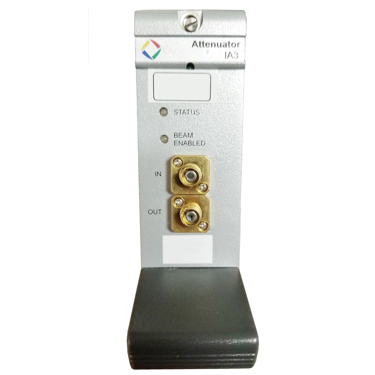
JDSU MAPA+2370290LC Dual-Channel Single-Mode Precision Optical Attenuator with Monitor Ports and LC Connectors
$2,872.00
Price in USD.
- Condition
- Used
- Availability
- In stock
- Model
- MAPA-2370290LC
- Manufacturer
- JDS
- Category
- Optical Attenuators 9-125
Description
JDSU MAPA+2370290LC Dual-Channel Single-Mode Precision Optical Attenuator with Monitor Ports and LC Connectors
The JDSU MAPA+2370290LC is a dual-channel single-mode precision optical attenuator cassette designed for compatible JDSU Multiple Application Platform systems. It integrates two identical variable optical attenuators into one cassette, providing independent attenuation channels for laboratory, production, DWDM, telecom, and automated optical test applications.
This configuration includes monitor ports and LC optical connectors. The monitor ports provide access to a portion of the optical signal for compatible external power measurement, calibration, or monitoring equipment. This allows users to observe optical power while the primary signal paths provide controlled attenuation.
The JDSU MAPA+2370290LC supports wavelengths from 1260 nm to 1650 nm and provides a 60 dB attenuation range on each channel. Attenuation can be adjusted with 0.001 dB setting resolution, supporting detailed optical loss simulation, receiver sensitivity testing, amplifier characterization, and precise optical power control.
Features and Benefits of the JDSU MAPA+2370290LC
The JDSU MAPA+2370290LC provides two precision attenuation channels for engineers, laboratories, production facilities, and service organizations working with single-mode fiber optic systems.
- Dual-channel configuration: Integrates two identical precision optical attenuators into one MAP cassette.
- Single-mode optical paths: Designed for compatible 9/125 µm single-mode fiber systems.
- Monitor ports: Provides separate optical monitor connections for compatible external power measurement equipment.
- LC optical connectors: Supports compact LC fiber connections for compatible optical test setups.
- Wide wavelength range: Operates across wavelengths from 1260 nm to 1650 nm.
- 60 dB attenuation range: Provides extensive optical loss adjustment for receiver, amplifier, and network simulation tests.
- Fine attenuation resolution: Supports attenuation settings in increments of 0.001 dB.
- Precise attenuation control: Provides attenuation accuracy of ±0.1 dB under the specified conditions.
- High repeatability: Provides attenuation repeatability of ±0.01 dB.
- Fast adjustment: Provides a nominal attenuation slew rate greater than 10 dB per second.
- High optical input capability: Accepts optical input power up to +23 dBm.
- Integrated shutter function: Provides optical isolation greater than 100 dB when the shutter is activated.
Dual-Channel Precision Attenuation
The dual-channel design allows two independent single-mode optical paths to be controlled from one MAP cassette. Each channel can be used with a separate source, receiver, device under test, or optical component path.
This architecture is useful for matched-path measurements, simultaneous device testing, bidirectional optical configurations, and test systems that require independent control of two optical signals. Combining two attenuators in one cassette also conserves chassis space compared with using two separate single-channel modules.
Each channel provides up to 60 dB of attenuation, excluding insertion loss. The 0.001 dB setting resolution allows very small changes in optical power to be programmed during detailed receiver sensitivity, linearity, threshold, and bit error rate measurements.
Monitor-Port Functionality
The monitor ports provide separate optical paths that can be connected to compatible external optical power meters. These ports can support monitoring of source-power changes, measurement of relative optical levels, and calibration of the relationship between the primary output and the monitor signal.
A monitor tap does not perform an optical power measurement by itself. A compatible external optical power meter or detector is required to measure the signal presented at each monitor port.
The monitor-path loss or tap ratio should be characterized for applications requiring calculated primary-path power from the monitor reading. Changes in wavelength, connector loss, polarization, and external cabling may affect the relationship between the monitor signal and the main optical output.
Precise Optical Power Control
The JDSU MAP Precision Attenuator family is designed for applications requiring controlled optical signal levels. Users can program a known attenuation value and determine the resulting output power from the input measurement, insertion loss, attenuation setting, and other optical path losses.
Attenuation accuracy is specified at ±0.1 dB under the defined reference conditions. Attenuation repeatability is ±0.01 dB at constant wavelength, temperature, and state of polarization.
The nominal attenuation slew rate is greater than 10 dB per second. This capability supports automated attenuation sweeps, receiver threshold measurements, bit error rate tests, optical power ramps, and production procedures requiring rapid changes in optical signal level.
DWDM and Telecom Test Applications
The wavelength range from 1260 nm to 1650 nm covers important single-mode telecom regions, including common test wavelengths around 1310 nm and 1550 nm. This broad coverage makes the cassette suitable for DWDM channel equalization, fiber-link loss simulation, amplifier testing, and wavelength-dependent component evaluation.
In a DWDM test system, the two attenuators can control separate channels or optical paths. The monitor ports can be connected to external detectors to observe the corresponding optical signals as attenuation settings are changed.
The module can also be combined with compatible MAP tunable lasers, optical power meters, switches, and other photonic instruments to form an integrated optical test station.
Typical Applications
The JDSU MAPA+2370290LC Precision Optical Attenuator is suitable for professional applications such as:
- Dual-channel single-mode optical attenuation
- DWDM channel equalization
- Optical amplifier characterization
- Bit error rate testing
- Receiver sensitivity measurement
- Transmitter and receiver evaluation
- Optical fiber-link loss simulation
- Precise optical power control
- Optical component characterization
- External optical power monitoring
- Production testing and quality control
- Automated MAP optical test systems
Product Overview
| Brand | JDSU / JDS Uniphase |
| Model | MAPA+2370290LC |
| Product Family | MAP Precision Attenuator |
| Product Category | Dual-Channel Precision Optical Attenuator |
| Channel Configuration | Two identical attenuator channels |
| Fiber Type | Single-mode fiber |
| Additional Optical Function | Monitor ports |
| Connector Configuration | LC |
| Compatible Platform | Compatible JDSU MAP chassis |
| Primary Application | Dual-channel attenuation and external power monitoring in single-mode optical test systems |
Single-Mode Attenuator Specifications
| Specification | JDSU MAPA+2370290LC Details |
| Number of Attenuation Channels | Two |
| Wavelength Range | 1260 nm to 1650 nm |
| Attenuation Range | 60 dB |
| Attenuation Setting Resolution | 0.001 dB |
| Attenuation Accuracy | ±0.1 dB |
| Attenuation Repeatability | ±0.01 dB |
| Nominal Attenuation Slew Rate | Greater than 10 dB per second, typical |
| Maximum Optical Input Power | +23 dBm |
| Shutter Isolation | Greater than 100 dB |
| Fiber Type | Single-mode fiber |
| Optical Connectors | LC |
Optical Performance Considerations
A standard single-mode MAP Precision Attenuator without a power-monitor function provides insertion loss of 1.5 dB or less at minimum attenuation. A configuration with an in-line power monitor provides insertion loss of 2.2 dB or less.
A separate monitor-tap coupler introduces additional optical loss that is not included in the base attenuator insertion-loss specification. The exact insertion loss of the MAPA+2370290LC configuration should therefore be verified through calibration data or performance testing.
Standard single-mode polarization-dependent loss is 0.05 dB or less. A single-mode configuration with an internal in-line power monitor has polarization-dependent loss of 0.15 dB or less. Actual performance of a monitor-tap configuration depends on the installed tap coupler and complete optical path.
| Performance Parameter | Standard Single-Mode Attenuator | Single-Mode Attenuator with In-Line Power Monitor |
| Insertion Loss at Minimum Attenuation | 1.5 dB or less | 2.2 dB or less |
| Polarization-Dependent Loss | 0.05 dB or less | 0.15 dB or less |
| Attenuation Range | 60 dB | 60 dB |
| Attenuation Accuracy | ±0.1 dB | ±0.1 dB |
Specification Conditions
Single-mode insertion-loss and attenuation specifications are defined at wavelengths of 1310 nm ±15 nm and 1550 nm ±15 nm. The insertion-loss measurement includes one mated pair of connectors but excludes additional tap-coupler loss when a monitor tap is installed.
Attenuation accuracy and repeatability are specified at an ambient temperature of 23 °C ±5 °C. Repeatability is measured at constant wavelength, constant temperature, and constant state of polarization.
The maximum attenuation-accuracy specification applies at 1310 nm ±15 nm and 1550 nm ±15 nm. Outside these wavelength regions, typical accuracy is the greater of ±0.1 dB or ±0.003 dB per dB of attenuation.
Environmental and Mechanical Specifications
| Specification | Details |
| Operating Temperature | 0 °C to 50 °C |
| Storage Temperature | -30 °C to 60 °C |
| Operating Humidity | Less than 90% relative humidity at 23 °C and less than 20% at 50 °C, non-condensing |
| Dimensions | 4.06 cm wide x 13.24 cm high x 39.5 cm deep |
| Dual-Cassette Weight | Approximately 1.3 kg |
| Warm-Up Time | 30 minutes |
| Recommended Calibration Period | Two years |
MAP Platform Integration
The JDSU MAPA+2370290LC requires a compatible MAP chassis for power, display, local control, attenuation adjustment, shutter operation, and automation access. The cassette does not operate as a complete standalone attenuator without a supported MAP platform or compatible controller configuration.
A MAP system can combine the dual attenuator with compatible tunable lasers, optical power meters, optical switches, and other photonic instruments. This enables integrated test stations for receiver evaluation, optical amplifier testing, DWDM component characterization, and automated manufacturing workflows.
Buyers should verify MAP chassis compatibility, available slot capacity, firmware support, automation interfaces, and the condition of the chassis module connector before installation.
Measurement Preparation and Connector Care
The MAP Precision Attenuator should complete its specified 30-minute warm-up period before precision measurements. The operating wavelength, attenuation values, shutter state, and monitor configuration should be verified before optical power is applied.
Input power must remain at or below the specified maximum of +23 dBm. Signals above this limit should be reduced before connection to protect the optical components.
All LC connector end faces should be inspected and cleaned before mating. Contamination can increase insertion loss, reduce return loss, cause instability, and affect attenuation repeatability.<