
Newport · 2930F-IG
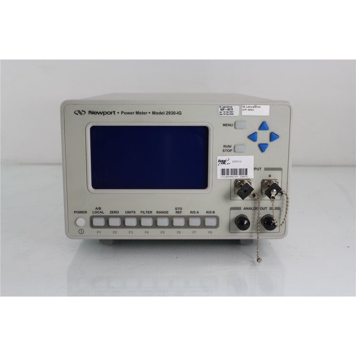
Newport 2930F-IG Dual-Channel InGaAs Fiber Optic Power Meter
$3,032.00
Price in USD.
- Condition
- Used
- Availability
- In stock
- Model
- 2930F-IG
- Manufacturer
- Newport
- Category
- Optical Power Meters (OPM)
Description
Newport 2930F-IG Dual-Channel InGaAs Fiber Optic Power Meter
The Newport 2930F-IG is a dual-channel optical power meter designed for continuous-wave measurements in fiber optic manufacturing, telecommunications testing, optical component development, laboratory research, and production environments. It combines two integrated 1 mm InGaAs detectors with independent measurement channels labeled A and B.
The dual-channel architecture allows optical power to be measured on channel A, channel B, or both channels. It also supports comparative measurements that use one channel as a reference for the other. This arrangement is useful for monitoring input and output power, measuring component transmission, comparing two optical paths, and evaluating source or system stability.
The F-Series configuration incorporates the detectors and fiber connector assemblies directly into the instrument. Unlike the 2930-C, the 2930F-IG does not require separate external detector heads and calibration modules for routine fiber-connected measurements. The IG designation identifies integrated InGaAs detectors.
The complete connector suffix should be verified from the physical instrument label. The 2930F-IG family was produced with FC-compatible or SC/PC optical interfaces. The specific unit should not be assigned an FC or SC connector type until the full model number and installed connectors have been confirmed.
Features and Benefits of the Newport 2930F-IG
- Dual-channel optical measurement: Provides independently controlled channel A and channel B inputs for simultaneous or comparative testing.
- Integrated InGaAs detectors: Uses two internal 1 mm InGaAs photodiodes for fiber optic continuous-wave power measurements.
- Direct fiber input: Accepts compatible fiber patch cords through the installed optical connector assemblies.
- Automatic and manual ranging: Selects a suitable signal range automatically or allows the operator to choose a range manually.
- Multiple measurement units: Supports watts, dBm, dB, relative measurements, detector current, and dual-channel mathematical functions where applicable.
- Zero correction: Subtracts stored background and detector-offset values from subsequent measurements.
- Reference measurements: Stores a measured value or uses the opposite channel as a reference for relative optical measurements.
- Selectable filtering: Provides analog, digital, combined analog and digital, or unfiltered measurement modes.
- Data storage and statistics: Stores up to 3,000 readings per channel and calculates minimum, maximum, mean, peak-to-peak difference, and standard deviation.
- External triggering: Synchronizes measurement acquisition with compatible external test equipment.
- Dual analog outputs: Provides one BNC analog output for each measurement channel.
- Computer interfaces: Includes GPIB, USB, and RS-232C communication for remote control and automated data acquisition.
- Graphical display: Uses a 240 x 128-pixel high-contrast LCD for measurements, settings, menus, and status information.
- Configuration storage: Saves frequently used operating configurations in non-volatile memory for later recall.
Dual InGaAs Measurement Channels
The 2930F-IG provides two optical measurement channels. Each channel has an integrated InGaAs detector and independently configurable measurement parameters.
Channel A and channel B can be started or stopped separately using dedicated front-panel controls. The main Run/Stop control can operate both channels simultaneously, allowing synchronized acquisition when two optical signals must be observed together.
This configuration is practical for measuring power before and after a device under test, comparing a test path against a reference path, monitoring two outputs from an optical component, or observing changes in two related signals during an experiment.
Integrated 1 mm InGaAs Detectors
The F-Series 2930F-IG incorporates two 1 mm InGaAs detectors. InGaAs photodiodes are used for compatible near-infrared fiber optic measurements, including common telecommunications applications.
Detector responsivity data is stored electronically within the power meter. The stored calibration information is applied according to the selected measurement wavelength, allowing the instrument to convert the measured photodiode current into optical power.
The supported wavelength range, optical power range, saturation threshold, and installed fiber connector must be confirmed from the complete unit configuration and calibration information. These detector-specific values should not be inferred from the abbreviated 2930F-IG designation alone.
Automatic and Manual Ranging
The instrument supports automatic and manual signal-range selection. In automatic mode, the meter chooses an appropriate measurement range based on the detector signal. In manual mode, the operator selects the range required for the application.
The meter provides up to seven decades of measurement range, depending on detector configuration and operating mode. Range changes occur in decade increments to make effective use of the internal analog-to-digital converters.
If the optical signal exceeds the selected range, the display indicates an overrange condition. If the detector signal reaches its stored saturation threshold, the meter reports a saturation condition.
Filtering and Stable Optical Measurements
The 2930F-IG provides four filtering choices: no filter, analog filtering, digital filtering, or combined analog and digital filtering.
The analog filter uses a 5 Hz low-pass response to reduce higher-frequency noise. Analog filtering affects both the displayed measurement and the associated analog output signal.
The digital filter uses a moving average of the most recent 16 readings. Its configurable measurement interval allows the operator to balance update speed and noise reduction according to the application.
Combined analog and digital filtering provides the noise-reduction benefits of both methods. Filtering can be configured independently for both optical channels.
Zero, Reference and Relative Measurements
The Zero function stores and subtracts detector offset and background signal from subsequent readings. This feature is useful for reducing the influence of dark current, ambient light, electronic offset, and other stable background conditions.
A source should be blocked or disabled before a zero value is established. Because detector and electronic offsets can change with temperature, the meter should be re-zeroed when measurement conditions change.
The Store Reference function saves the latest reading for relative measurements. On the dual-channel 2930F-IG, the opposite measurement channel can also serve as a live reference source.
Relative results can be displayed as a linear ratio or in decibels. This supports insertion loss, transmission, gain, and comparative optical measurements.
Data Storage and Statistics
The power meter can store up to 3,000 readings per channel in internal measurement buffers. Separate data-storage settings are available for channel A and channel B.
Fixed-buffer operation collects readings until the selected data buffer is full. Sliding-buffer operation continually retains the newest readings while removing the oldest values after the buffer reaches its configured capacity.
Available storage intervals include 1, 10, 20, 50, 100, and 1,000 milliseconds. Stored readings can be retrieved through a supported computer interface.
The instrument calculates minimum, maximum, mean, maximum-minus-minimum, and standard-deviation values from the collected measurement data. These statistical functions support stability checks, production monitoring, repeatability evaluation, and optical source characterization.
External Triggering
A rear-panel BNC trigger input allows the 2930F-IG to synchronize measurements with compatible external equipment. The trigger can be configured for a rising or falling edge.
A programmable holdoff from 0 to 1,000 milliseconds delays the measurement after the trigger event. This can accommodate settling time from optical switches, attenuators, sources, mechanical systems, or devices under test.
External triggering can be enabled for channel A, channel B, or both channels. When the holdoff is set to zero, the meter normally acquires the reading approximately 250 to 750 microseconds after the trigger event.
Dual Analog Outputs
The 2930 Series provides two BNC analog outputs, one for each optical measurement channel. Each analog output delivers the amplified detector signal for direct monitoring with compatible oscilloscopes, voltmeters, data-acquisition systems, or control equipment.
The full-scale analog output is 0 V to 5 V into a 1 MO load or 0 V to 2.5 V into a 50O load.
The analog output is not corrected for detector responsivity, wavelength calibration, instrument auto-calibration, or stored zero values. External equipment must account for the selected signal range and detector response when converting the analog voltage into optical power.
Remote Control and Automated Testing
The Newport 2930F-IG includes GPIB, USB, and RS-232C interfaces. These connections enable remote configuration, measurement acquisition, data retrieval, status reporting, and automated test-system integration.
The GPIB interface supports IEEE 488.1 hardware and IEEE 488.2 software conventions. The GPIB address can be set from 1 to 30.
The RS-232C interface supports communication rates of 300, 1,200, 2,400, 4,800, 9,600, 19,200, and 38,400 baud with eight data bits, no parity, and one stop bit.
Remote commands allow users to control channel acquisition, wavelength settings, measurement units, filtering, ranging, zeroing, reference values, data storage, triggering, and status reporting.
Typical Applications
- Dual-channel fiber optic power measurement
- Continuous-wave optical source testing
- Fiber optic component manufacturing
- Insertion loss and transmission measurements
- Input and output power comparison
- Optical source stability monitoring
- Telecommunications laboratory testing
- Optical amplifier and attenuator evaluation
- Fiber optic switch and coupler testing
- Production screening and quality assurance
- Automated optical measurement systems
- Photonics research and development
Product Overview
| Brand | Newport |
| Model | 2930F-IG |
| Product Series | 1930/2930 Series |
| Product Category | Dual-Channel Fiber Optic Power Meter |
| Measurement Channels | Two, channel A and channel B |
| Detector Type | Two integrated 1 mm InGaAs photodiodes |
| Measurement Type | Continuous-wave optical power |
| Optical Connector | FC-compatible or SC/PC depending on complete model suffix |
| Analog Outputs | Two BNC outputs |
| Remote Interfaces | GPIB, USB, and RS-232C |
| Primary Application | Dual-channel continuous-wave fiber optic power measurement |
Known System Specifications
| Specification | Details |
| Display | 240 x 128-pixel high-contrast graphical LCD |
| Measurement Update Rate | 10 Hz |
| Measurement Ranges | Up to seven decades, depending on detector and operating mode |
| Data Storage | Up to 3,000 measurements per channel |
| Digital Filter | Moving average of 16 readings |
| Analog Filter | 5 Hz low-pass filter |
| External Trigger | BNC input with rising- or falling-edge selection |
| Trigger Holdoff | 0 to 1,000 ms |
| Analog Output | 0 V to 5 V into 1 MO or 0 V to 2.5 V into 50O |
Physical, Electrical and Environmental Specifications
| Specification | Details |
| Dimensions | Approximately 345 x 216 x 139 mm |
| Weight | Approximately 2.7 kg |
| Enclosure | Powder-coated metal case |
| AC Input | 100/120 V AC or 220/240 V AC, ±10% |
| Line Frequency | 50/60 Hz |
| Power Consumption | 38 VA |
| Operating Temperature | 10 °C to 45 °C |
| Operating Humidity | Less than 85% relative humidity, non-condensing |
| Maximum Operating Altitude | 2,000 m |
| Storage Temperature | -20 °C to +60 °C |
| Storage Humidity | Less than 90% relative humidity, non-condensing |
| Intended Environment | Indoor use |
Communication Specifications
| Interface | Details |
| GPIB | IEEE 488.1 hardware and IEEE 488.2 software compatibility |
| GPIB Address Range | 1 to 30 |
| USB | Supported for remote communication with compatible drivers |
| RS-232C Rates | 300, 1,200, 2,400, 4,800, 9,600, 19,200, or 38,400 baud |
| RS-232C Format | Eight data bits, no parity, and one stop bit |
| Trigger Input | BNC connector for TTL/CMOS-compatible edge triggering |
| Analog Outputs | Two BNC connectors, one per channel |
Connector Configuration Verification
The abbreviated model 2930F-IG confirms a dual-channel F-Series power meter with integrated InGaAs detectors. It does not identify the installed fiber connector.
| Complete Model | Connector Configuration |
| 2930F-IG-FC | FC-compatible optical inputs supporting PC- and APC-style patch cord connectors |
| 2930F-IG-SC | SC/PC optical inputs |
The complete rear or front-panel model label and the physical optical interfaces should be inspected before connector compatibility is assigned to the product listing.
Measurement Setup
The meter should be connected to a properly grounded AC receptacle with its voltage selector set for the available facility power. The selected voltage and installed fuse ratings must correspond.
The instrument should warm up for at least 60 minutes before measurements requiring specified accuracy are recorded. An A/D offset calibration should then be completed for each channel.
The correct source wavelength should be entered independently for channels A and B. The meter uses the selected wavelength and stored detector responsivity data to calculate optical power.
Before establishing a zero reference, the optical source should be blocked or disabled. The source can then be restored and the optical power measured in watts, dBm, dB, or another supported unit.
Comprehensive Functional and Performance Testing
The Newport 2930F-IG receives comprehensive functional and performance testing before shipment. Evaluation may include AC power operation, startup self-test, graphical display, backlight, front-panel controls, independent channel operation, automatic and manual ranging, filtering, zeroing, reference storage, data storage, statistics, and external triggering.
Optical testing may include response from both integrated InGaAs detectors, wavelength-setting operation, relative measurement functions, channel-to-channel comparison, saturation reporting, and analog output response using suitable optical sources and calibrated reference equipment.
Communication testing may include GPIB, USB, and RS-232C operation. The optical inputs, BNC outputs, trigger input, communication ports, AC inlet, voltage selector, fuse holders, display, controls, enclosure, labels, and calibration markings may be inspected for damage, contamination, or excessive wear.
The exact testing scope depends on the installed FC or SC connector option, available optical wavelengths, calibrated optical references, patch cords, computer interfaces, and requested measurement points.
Calibration Before Shipment
When technically applicable and selected, the Newport 2930F-IG can be calibrated or performance-verified before shipment. Evaluation may include both integrated InGaAs detector channels, detector responsivity, optical power accuracy, channel matching, linearity, range operation, zero offset, wavelength correction, analog outputs, and communication interfaces.
The integrated detector assemblies store responsivity data measured at 10 nm increments. The instrument interpolates between stored calibration points when a wavelength between two calibration values is selected.
Calibration documentation should identify the meter model and serial number, channel, installed connector type, test wavelength, optical power, selected range, filters, reference equipment, environmental conditions, measured results, and applicable uncertainty.
Annual recalibration is recommended to maintain confidence in optical power measurement accuracy and detector traceability.
Buyer Considerations
Buyers should confirm the complete model number as either 2930F-IG-FC or 2930F-IG-SC. The connector style should also be verified from the physical optical inputs before compatible patch cords are selected.
The condition of both integrated detector assemblies should be reviewed. Contaminated, damaged, or incorrectly mated optical interfaces can affect measured power and repeatability.
The listing should identify whether the AC power cord, USB cable, RS-232 cable, GPIB cable, fiber patch cords, connector adapters, software, manual, calibration report, or other accessories are included.
Only the Newport 2930F-IG optical power meter and accessories specifically identified in the product listing should be considered included.
Why Buy from AssetRelay?
AssetRelay supplies professional equipment and product solutions for fiber optic, telecommunications, optical testing, photonics, laboratory, production, inspection, electronic testing, RF/microwave, and technical research applications. The Newport 2930F-IG provides dual-channel optical power measurement for component manufacturers, telecommunications laboratories, production facilities, system integrators, universities, and research organizations.
Buyers should review the complete model suffix, optical connector configuration, operation of both InGaAs channels, display, controls, analog outputs, communication interfaces, calibration status, functional test results, and included accessories before purchase.