
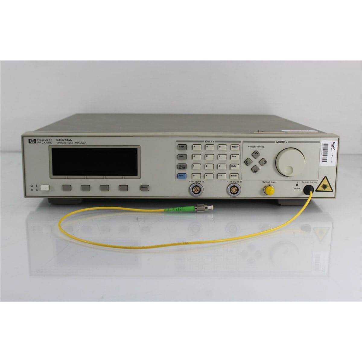
HP · E5574A_135_20
HP E5574A-135-020 Dual-Wavelength Optical Loss Analyzer with Bare Fiber Pigtail Output
$3,192.00
Price in USD.
- Condition
- Used
- Availability
- In stock
- Model
- E5574A_135_20
- Manufacturer
- HP
- Category
- Return Loss Meters (RLM)
Description
HP E5574A-135-020 Dual-Wavelength Optical Loss Analyzer
The HP E5574A-135-020 is a precision optical loss analyzer configured for characterization of active and passive optical components at 1310 nm and 1550 nm. Option 135 provides integrated dual-wavelength Fabry-Perot laser sources, while Option 020 provides a bare fiber pigtail optical output optimized for high-performance polarization-dependent measurements.
The HP E5574A combines optical power measurement and polarization analysis within one modular test platform. It is designed to measure insertion loss, optical gain, polarization-dependent loss, polarization-dependent gain, and polarization-dependent crosstalk. These functions support component engineering, incoming inspection, process development, production testing, qualification, and laboratory research.
The analyzer is especially suited to optical components whose transmission or gain changes according to the input state of polarization. It can evaluate the different contributions to total device loss without requiring a separate PDL reference measurement. This integrated approach helps simplify optical setups and supports repeatable manual or automated testing.
Features and Benefits of the HP E5574A-135-020
- Dual integrated wavelengths: Option 135 combines 1310 nm and 1550 nm Fabry-Perot laser sources in one analyzer.
- Bare fiber pigtail output: Option 020 provides a pigtailed interface for high-performance polarization-dependent measurements.
- Comprehensive loss analysis: Supports insertion loss, gain, PDL, PDG, and PDCR characterization.
- High PDL/PDG accuracy: Provides absolute uncertainty beginning at ±0.005 dB for supported measurements.
- Fine measurement display: Offers 0.0001 dB display resolution for observing small optical changes.
- No separate PDL reference required: Simplifies polarization-dependent measurement setup and operation.
- Broad external-source support: Accepts compatible external sources for measurements from 1250 nm to 1600 nm.
- Interchangeable optical heads: Supports selected optical heads covering wavelengths from 800 nm to 1700 nm.
- Wide detector power coverage: Available optical heads support selected input levels from +27 dBm to -90 dBm.
- Up to 20 dB device loss: Characterizes devices under test with insertion loss as high as 20 dB.
- HP-IB automation: Supports integration into compatible automated laboratory and production systems.
- Active and passive component testing: Suitable for filters, couplers, amplifiers, isolators, circulators, switches, and related devices.
Dual 1310 nm and 1550 nm Laser Sources
The -135 configuration includes dual Fabry-Perot laser sources at 1310 nm and 1550 nm. These wavelengths cover two principal transmission regions used by single-mode fiber optic systems and components.
The integrated 1310 nm source supports component evaluation in the O-band region, while the 1550 nm source supports testing in the C-band region used by many long-haul, WDM, optical amplifier, and photonics applications.
Housing both wavelengths in one analyzer reduces the need to reconnect separate external sources when switching between 1310 nm and 1550 nm measurements. This supports more efficient component comparison, dual-wavelength qualification, and production testing.
The source wavelengths should be selected according to the operating range of the device under test. Components intended for only one wavelength region should not be assumed to provide equivalent performance at the other integrated wavelength.
Bare Fiber Pigtail Optical Output
Option 020 provides a bare fiber pigtail output. The pigtailed interface is intended to deliver strong polarization measurement performance while allowing the output fiber to be prepared or connected according to the requirements of the test setup.
A bare fiber output can be fusion spliced to a compatible test cable, installed in a temporary bare fiber fixture, or terminated using an appropriate connectorization process. The selected method should preserve single-mode operation and avoid introducing excessive loss, reflection, mechanical stress, or polarization instability.
The pigtail should be handled carefully and protected from tight bends, pulling, twisting, crushing, contamination, and damaged coating. Mechanical stress can affect optical loss and the state of polarization delivered to the device under test.
Insertion Loss and Optical Gain Measurements
The HP E5574A measures changes in optical power introduced by active and passive devices. For a passive device, the analyzer can determine insertion loss by comparing the optical power before and after the component.
For an active device such as an optical amplifier, the system can characterize gain by comparing the output power with the optical input under defined operating conditions.
Accurate measurements require a stable optical reference, suitable optical heads, clean connections, compatible fiber, and an appropriate reference procedure. The source wavelength, source power, detector head, device operating conditions, and fiber routing should remain controlled throughout the measurement sequence.
Polarization-Dependent Loss Measurement
Polarization-dependent loss describes the change in insertion loss as the state of polarization applied to a passive optical component varies. The HP E5574A is optimized for measuring these small polarization-related changes.
The analyzer supports absolute PDL measurements from 0 dB to 5 dB. For measured PDL values up to 0.2 dB, absolute uncertainty is specified at ±0.005 dB with an additional asymmetric term of +0/-2.5% of the measured PDL.
For PDL values greater than 0.2 dB and up to 5 dB, absolute uncertainty is specified at ±0.005 dB with an additional asymmetric term of +0/-5% of the measured PDL.
The analyzer complies with Fiber-Optic Test Procedure FOTP-157 for applicable polarization-dependent loss measurements.
Polarization-Dependent Gain Measurement
Polarization-dependent gain describes the variation in optical gain produced by an active component as the input state of polarization changes. This measurement is important for optical amplifiers and other active devices that may respond differently to changing polarization conditions.
The E5574A applies the same documented 0 dB to 5 dB measurement range and absolute uncertainty structure to supported PDG measurements. This enables detailed characterization of optical amplifiers, gain modules, and related active photonic components.
Device bias, pump conditions, wavelength, input power, output power, warm-up, and thermal stability should remain controlled during PDG testing. Changes in these conditions can influence results independently of polarization.
Polarization-Dependent Crosstalk Ratio
The HP E5574A also supports polarization-dependent crosstalk ratio measurements from 0 dB to 5 dB. PDCR measurement is useful for devices in which optical isolation or crosstalk varies with the input polarization state.
For PDCR values up to 0.2 dB, absolute uncertainty is specified at ±0.01 dB with an additional asymmetric term of +0/-5% of the measured PDCR.
For PDCR values greater than 0.2 dB and up to 5 dB, absolute uncertainty is specified at ±0.01 dB with an additional asymmetric term of +0/-10% of the measured PDCR.
Fine Display Resolution and Repeatability
The analyzer provides 0.0001 dB display resolution. This fine numerical resolution allows operators to observe small changes during device adjustment, polarization analysis, component comparison, and process optimization.
PDL and PDG repeatability is specified at ±0.001 dB plus 2% of the measured PDL. PDCR repeatability is specified at ±0.002 dB plus 4% of the measured PDCR.
Display resolution should not be interpreted as complete measurement accuracy. Final uncertainty also depends on the selected optical head, wavelength, power level, device loss, polarization control, connection stability, reference procedure, and environmental conditions.
External Tunable and Broadband Source Support
In addition to its integrated dual-wavelength sources, the HP E5574A can work with a compatible external tunable laser or white-light source for wavelength-dependent measurements.
With a suitable external source, the documented analyzer wavelength range is 1250 nm to 1600 nm. This supports swept-wavelength characterization of filters, couplers, isolators, amplifiers, switches, and other devices whose optical response varies across wavelength.
The external source, wavelength-control system, polarization controller, and optical head must be compatible with the required measurement range and test method. External sources and related accessories should not be considered included unless specifically identified in the product listing.
Interchangeable Optical Measurement Heads
The E5574A supports a selection of interchangeable HP optical heads. Available detector configurations cover selected wavelengths from 800 nm to 1700 nm and optical power levels from +27 dBm to -90 dBm.
The appropriate optical head should be selected according to the source wavelength, expected power, device insertion loss or gain, required measurement uncertainty, and polarization performance.
For the best PDL measurement performance between 1250 nm and 1600 nm, the HP 81521B Option 001 optical head is recommended. Option 521 adds a second HP 81521B Option 001 optical head to supported E5574A configurations.
One compatible HP 81000xA connector adapter is required for each installed optical head. Connector interfaces appropriate for the optical input and output are also required according to the configured measurement path.
Compatible Polarization Controllers
The HP E5574A can be integrated with compatible HP automatic polarization controllers for complete polarization-state adjustment and analysis. Supported system configurations may use the HP 11896A or HP 8169A polarization controller.
The HP 11896A uses a fiber-loop design to generate all states of polarization with very low insertion-loss variation. It operates from 1250 nm to 1600 nm and provides insertion-loss variation below ±0.002 dB during adjustment.
The HP 8169A uses a built-in linear polarizer, quarter-wave plate, and half-wave plate to synthesize defined states of polarization. It operates from 1470 nm to 1570 nm and supports deterministic movement between polarization states.
A polarization controller should be considered included only when it is specifically identified in the product listing.
Typical Applications
- Insertion-loss measurement of passive optical components
- Optical amplifier gain characterization
- Polarization-dependent loss measurement
- Polarization-dependent gain measurement
- Polarization-dependent crosstalk analysis
- 1310 nm and 1550 nm component testing
- Optical filter and coupler characterization
- Optical isolator and circulator testing
- Fiber optic switch evaluation
- WDM and telecommunications component qualification
- Photonics research and development
- Automated optical production testing
Product Overview
| Brand | HP |
| Base Model | E5574A |
| Configuration | E5574A-135-020 |
| Product Category | Optical Loss and Polarization Analyzer |
| Option 135 | Dual-wavelength 1310 nm and 1550 nm Fabry-Perot laser sources |
| Option 020 | Bare fiber pigtail optical output |
| Primary Measurements | Insertion loss, optical gain, PDL, PDG, and PDCR |
| Control Interface | HP-IB |
| Primary Application | Loss, gain, and polarization characterization of active and passive optical components |
Integrated Source Configuration
| Configuration Item | Details |
| Source Option | Option 135 |
| First Source Wavelength | 1310 nm |
| Second Source Wavelength | 1550 nm |
| Source Type | Fabry-Perot laser |
| Output Option | Option 020 |
| Optical Output Interface | Bare fiber pigtail |
Polarization Measurement Specifications
| Specification | Details |
| Display Resolution | 0.0001 dB |
| PDL/PDG/PDCR Measurement Range | 0 dB to 5 dB |
| Absolute PDL/PDG Uncertainty at 0 to 0.2 dB | ±0.005 dB with an additional +0/-2.5% of the measured PDL |
| Absolute PDL/PDG Uncertainty Above 0.2 to 5 dB | ±0.005 dB with an additional +0/-5% of the measured PDL |
| PDL/PDG Repeatability | ±0.001 dB plus 2% of the measured PDL |
| Absolute PDCR Uncertainty at 0 to 0.2 dB | ±0.01 dB with an additional +0/-5% of the measured PDCR |
| Absolute PDCR Uncertainty Above 0.2 to 5 dB | ±0.01 dB with an additional +0/-10% of the measured PDCR |
| PDCR Repeatability | ±0.002 dB plus 4% of the measured PDCR |
| Supported Test Procedure | Fiber-Optic Test Procedure FOTP-157 |
System Measurement Capabilities
| Specification | Details |
| External-Source Wavelength Range | 1250 nm to 1600 nm |
| Maximum Device Insertion Loss | 20 dB |
| Available Optical Head Wavelength Coverage | Selected configurations from 800 nm to 1700 nm |
| Available Optical Head Power Coverage | Selected configurations from +27 dBm to -90 dBm |
| Recommended High-Performance PDL Head | HP 81521B Option 001 for measurements from 1250 nm to 1600 nm |
| Power Measurement Accuracy | 2.2% for the documented system configuration |
| PDL Reference Measurement | Not required |
Documented E5574A Options
| Option | Description |
| 013 | 1310 nm Fabry-Perot laser source |
| 015 | 1550 nm Fabry-Perot laser source |
| 135 | Dual-wavelength laser source |
| 020 | Bare fiber pigtail output |
| 021 | Straight-contact connector output |
| 022 | Angled-contact connector output |
| 521 | Adds a second HP 81521B Option 001 optical head |
Optical Head and Adapter Requirements
The E5574A requires a compatible optical measurement head appropriate for the wavelength and power range of the intended application. The source configuration alone does not establish the detector model or input connector installed in the analyzer.
One compatible HP 81000xA connector adapter is required for each optical head. A suitable connector interface is also required for both the optical output and optical input according to the selected E5574A configuration.
The HP 81521B Option 001 optical head is recommended when the highest supported PDL measurement performance is required between 1250 nm and 1600 nm. The installed optical head and adapter should be confirmed from the equipment labels and product photographs.
Connection and Measurement Considerations
The bare output pigtail should be inspected for coating damage, tight bends, cracks, contamination, mechanical stress, and previous splices. The fiber should be secured so movement does not alter the optical connection or polarization state during measurement.
When fusion splicing the output to a test cable, the fiber types should be compatible and the splice should be protected from stress. The splice loss and any polarization effects introduced by the connection should be considered in the measurement setup.
All connectorized interfaces should be inspected and cleaned before use. Contamination can introduce loss, reflection, instability, and measurement errors.
The device under test should remain within the analyzer’s maximum supported insertion loss and the selected optical head’s input-power range. Active devices should be allowed to stabilize before gain or PDG readings are recorded.
Calibration Before Shipment
When technically applicable and selected, the HP E5574A-135-020 can be calibrated or performance-verified before shipment. Calibration may include optical power measurement, insertion-loss accuracy, source operation at 1310 nm and 1550 nm, display response, PDL/PDG measurement performance, PDCR measurement performance, and HP-IB communication.
A full optical system calibration requires the analyzer, installed optical head or heads, connector adapters, output interface, polarization controller, optical reference cables, and suitable calibrated sources or standards. Each optical head should be identified by model and serial number in the calibration documentation.
Buyers requiring formal calibration should confirm the required wavelengths, optical power levels, insertion-loss points, PDL or PDG values, optical head configuration, output pigtail condition, certificate type, recorded results, and measurement uncertainty before purchase.
Comprehensive Functional and Performance Testing
The HP E5574A-135-020 receives comprehensive functional and performance testing before shipment. Evaluation may include power-up, display operation, control response, option recognition, source selection, 1310 nm output, 1550 nm output, optical head recognition, measurement functions, reference operations, and HP-IB communication.
Optical testing may include dual-wavelength source verification, optical power response, insertion-loss measurement, gain measurement, PDL/PDG operation, PDCR operation, and repeatability using compatible reference equipment.
The output pigtail, optical heads, connector adapters, input interfaces, and internal or external optical paths may be inspected for contamination, damaged fiber, worn adapters, loose mounting, or other conditions that could affect measurement performance.
The exact testing scope depends on the installed optical head, connector adapters, polarization controller, pigtail termination, available calibrated sources, reference detectors, optical standards, and supporting test equipment.
Buyer Considerations
Buyers should confirm the complete configuration as HP E5574A with Option 135 and Option 020. Option 135 identifies the dual-wavelength laser source configuration, while Option 020 identifies the bare fiber pigtail output.
The installed optical head or heads should be identified before purchase. Optical head wavelength range, power range, adapter type, connector interface, and calibration status determine the analyzer’s complete measurement capability.
The product listing should identify whether a polarization controller, optical heads, HP 81000-series adapters, optical cables, external source, HP-IB cable, software, manuals, calibration records, or other accessories are included.
The condition of the display, controls, internal sources, bare output pigtail, optical head ports, adapters, HP-IB interface, enclosure, cooling openings, power inlet, and identification labels should be reviewed before purchase.
Only the analyzer, installed source options, optical heads, connector adapters, output pigtail, polarization controller, cables, software, documentation, calibration records, and accessories specifically identified in the product listing should be considered included.
Why Buy from AssetRelay?
AssetRelay supplies professional equipment and product solutions for fiber optic, telecom, laboratory, production, optical test, photonics, electronic test, RF/microwave, inspection, and technical research applications. The HP E5574A-135-020 provides dual-wavelength loss, gain, and polarization analysis for optical component manufacturers, telecommunications laboratories, amplifier developers, system integrators, production facilities, and research organizations.
Buyers should review the product photographs, complete option configuration, source operation, pigtail condition, installed optical heads, connector adapters, polarization-controller compatibility, calibration status, functional test results, and included accessories before purchase.