
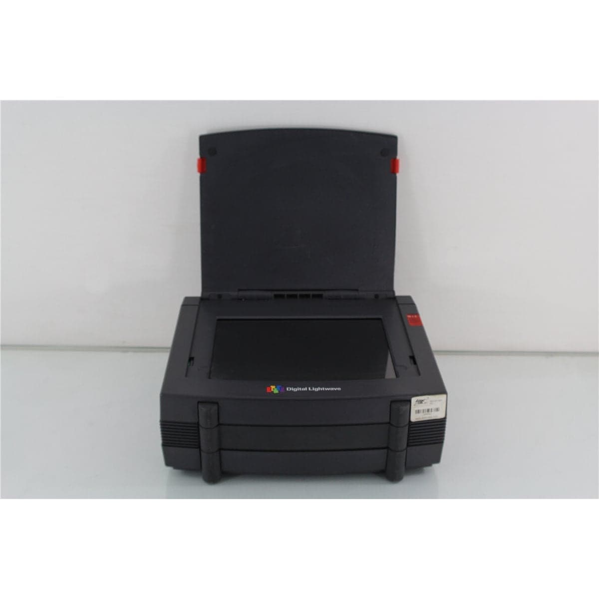
Digital-Lightwave · NIC25G-A00-E02
Digital Lightwave NIC2.5G-A00-E02-H121-J00-L71 Network Information Computer
$2,400.00
Price in USD.
- Condition
- Used
- Availability
- In stock
- Model
- NIC25G-A00-E02
- Manufacturer
- Digital-Lightwave
- Category
- Network Testers
Description
Digital Lightwave NIC2.5G-A00-E02-H121-J00-L71 Network Information Computer
The Digital Lightwave NIC2.5G-A00-E02-H121-J00-L71 is a portable telecommunications test platform designed for supported optical and electrical network testing applications. As part of the NIC 2.5G Network Information Computer family, the instrument combines test configuration, signal monitoring, alarm and error analysis, results management, and remote-control capabilities in an integrated field and laboratory platform.
The NIC 2.5G architecture was developed for telecommunications professionals working with high-speed digital transmission equipment and fiber optic networks. Depending on the hardware, software, and licensed options installed in an individual instrument, the platform can support compatible network installation, commissioning, service activation, maintenance, troubleshooting, equipment qualification, and production workflows.
The complete NIC2.5G-A00-E02-H121-J00-L71 model designation is important because the suffixes identify a unit-specific configuration. The option code should remain intact in the product listing. Individual protocol support, optical wavelengths, electrical interfaces, jitter functions, transmission rates, connector formats, and licensed applications should be confirmed from the instrument’s system-information menus, physical ports, startup screens, and identification labels.
The instrument is designed as a self-contained test platform with an integrated color touchscreen. The graphical interface allows users to configure supported signal paths, select test applications, monitor test status, review alarms and errors, and access stored results without requiring a separate computer for routine operation.
Features and Benefits of the Digital Lightwave NIC2.5G
The NIC2.5G-A00-E02-H121-J00-L71 provides an integrated platform for professional telecommunications users who require configurable test functions in field, laboratory, service, or production environments.
- Portable telecommunications test platform: Combines supported optical and electrical network test functions in one integrated instrument.
- Option-coded configuration: The complete A00-E02-H121-J00-L71 suffix identifies the installed unit-specific hardware and software arrangement.
- Integrated color touchscreen: Provides direct access to supported test configurations, measurements, alarms, errors, and saved results.
- Graphical test setup: Simplifies compatible signal routing and measurement configuration through a visual operating interface.
- Network troubleshooting support: Helps technicians monitor supported signals and investigate transmission alarms, errors, and service problems.
- Field and laboratory operation: Suitable for telecommunications installation, maintenance, equipment development, qualification, and production testing.
- Remote-control capability: Supports integration into compatible automated and computer-controlled test environments when the required interfaces and software are installed.
- Results management: Provides a platform for reviewing, storing, and transferring supported test configurations and measurement results.
- Serviceable legacy platform: Supports replacement, expansion, and continued operation of compatible Digital Lightwave test environments.
Network Installation and Commissioning
The Digital Lightwave NIC 2.5G can be used during supported telecommunications network installation and commissioning workflows. The instrument allows technicians to configure compatible test signals, monitor received traffic, review alarms, and evaluate circuit behavior before a service is placed into operation.
A commissioning procedure may include verifying physical interfaces, confirming signal detection, checking framing or synchronization, monitoring error conditions, and documenting test results. The exact procedure depends on the interfaces and applications installed in the individual NIC2.5G configuration.
The option-coded hardware should be inspected before the instrument is connected to live network equipment. Optical wavelength, transmission rate, connector type, electrical level, impedance, framing, line code, and maximum input limits must match the circuit under test.
Maintenance and Troubleshooting
The NIC2.5G-A00-E02-H121-J00-L71 can support maintenance and troubleshooting of compatible telecommunications equipment. Its integrated display provides a centralized interface for observing supported signal conditions and reviewing active or historical alarms and errors.
Troubleshooting can include checking whether a signal is present, identifying a framing or synchronization issue, evaluating error conditions, comparing transmitted and received test patterns, or isolating a problem between network elements.
The instrument should be configured according to the applicable network standard and circuit parameters before test traffic is generated or a monitoring connection is made. Incorrect test settings can produce invalid results or disrupt an active service.
Optical Interface Considerations
The exact optical configuration of the NIC2.5G-A00-E02-H121-J00-L71 should be verified directly from the instrument. Optical wavelength, transmitter output, receiver input range, connector family, ferrule polish, fiber type, and supported transmission rate can vary according to the installed hardware options.
Every optical port and mating patch cord should be inspected before connection. Contaminated fiber end faces can increase insertion loss, create reflections, reduce signal quality, and transfer debris to the instrument.
Physical-contact and angled physical-contact connectors must not be directly intermated. Connector family and ferrule polish should be confirmed before patch cords or adapters are selected.
When an optical source level is unknown, a suitable optical power meter or attenuator should be used before the signal is connected to the instrument. The maximum permissible receiver input must not be exceeded.
Electrical Interface Considerations
Supported electrical interfaces depend on the installed NIC 2.5G configuration. Each electrical port should be identified before connection, including its intended signal type, connector, impedance, input or output direction, and maximum allowable level.
Compatible cables and terminations should be used for the applicable transmission standard. Improper impedance or cable selection can cause reflections, signal distortion, framing errors, intermittent operation, and incorrect measurement results.
Test-pattern generation and error insertion should only be used on circuits where active testing is permitted. Monitor or bridging configurations should be selected when a live signal must be observed without intentionally disrupting traffic.
Integrated Touchscreen Interface
The NIC 2.5G platform uses an integrated color touchscreen for system control and results display. The graphical interface provides access to supported applications, signal routing, setup parameters, measurement status, alarms, error counts, and stored information.
Touchscreen operation reduces dependence on an external keyboard or controller during field testing. The display also allows the technician to review several related measurement parameters from one portable platform.
The touchscreen should be checked for accurate response across the complete display area. Damage, calibration errors, dead regions, image distortion, or reduced backlight performance can affect field usability.
Remote Operation and Automation
The NIC 2.5G platform can support remote operation through compatible communication interfaces and software. Remote control allows the instrument to be integrated into laboratory automation, production testing, environmental testing, and unattended monitoring systems.
Available remote interfaces and commands depend on the installed hardware, operating software, firmware revision, and licensed options. These capabilities should be confirmed directly from the individual instrument before integration.
Computer compatibility, communication cables, interface adapters, network settings, drivers, and remote-control software should also be verified. Legacy software may require a compatible operating-system environment.
Typical Applications
The Digital Lightwave NIC2.5G-A00-E02-H121-J00-L71 is suitable for supported professional applications such as:
- Telecommunications network installation
- Service activation and commissioning
- Optical transmission-system testing
- Electrical digital-network testing
- Alarm and error monitoring
- Transmission-equipment troubleshooting
- Network maintenance and repair
- Equipment qualification and acceptance testing
- Laboratory telecommunications research
- Production and quality-control testing
- Automated test-system integration
- Legacy Digital Lightwave system support
Product Overview
| Brand | Digital Lightwave |
| Model | NIC2.5G-A00-E02-H121-J00-L71 |
| Product Family | NIC 2.5G Network Information Computer |
| Product Category | Portable Telecommunications Test Platform |
| Operating Interface | Integrated color touchscreen |
| Configuration Type | Unit-specific option-coded hardware and software configuration |
| Primary Application | Installation, qualification, maintenance, and troubleshooting of compatible telecommunications networks |
Complete Configuration Code
| Configuration Element | Identification |
| Base Platform | NIC2.5G Network Information Computer |
| Option Group 1 | A00 |
| Option Group 2 | E02 |
| Option Group 3 | H121 |
| Option Group 4 | J00 |
| Option Group 5 | L71 |
Installed Capabilities Requiring Verification
| Configuration Item | Verification Required |
| Supported Protocols | Review startup menus and system information for installed telecommunications applications |
| Maximum Test Rate | Confirm the highest supported optical or electrical transmission rate |
| Optical Wavelengths | Confirm all installed transmitter and receiver wavelength configurations |
| Optical Connector Type | Confirm connector family and ferrule polish from each optical port |
| Optical Power Limits | Confirm transmitter output and receiver maximum input before connection |
| Electrical Interfaces | Identify connector types, signal standards, direction, and impedance |
| Jitter Functions | Confirm installed generation, measurement, filtering, and mask capabilities |
| Licensed Software | Review installed applications, licenses, firmware, and software revision |
| Remote Interfaces | Confirm available serial, GPIB, Ethernet, or other control connections |
| Storage Hardware | Confirm installed internal storage, removable-media interfaces, and data-transfer options |
Installation and Initial Setup
The Digital Lightwave NIC 2.5G should be placed on a stable surface with sufficient clearance for ventilation, test cables, optical patch cords, AC power, and operator access. Cooling openings should remain unobstructed during operation.
The AC input requirements shown on the instrument should be verified before power is applied. The power cord and protective-ground connection must be appropriate for the installation location.
After startup, the model number, serial number, software version, firmware revision, installed applications, and detected hardware options should be recorded. This information helps establish the actual capabilities of the individual analyzer.
Optical and electrical ports should be inspected before test cables are attached. Initial testing should use conservative levels and known reference signals until correct operation has been confirmed.
Comprehensive Functional and Performance Testing
The Digital Lightwave NIC2.5G-A00-E02-H121-J00-L71 receives comprehensive functional and performance testing before shipment. Evaluation may include AC power operation, startup, display condition, touchscreen response, internal storage, cooling, audio indicators, and installed software recognition.
Interface testing may include operation of available optical ports, electrical ports, communication interfaces, trigger connections, and removable-media hardware. Supported test applications may be checked using compatible reference signals and network equipment.
Protocol testing may include signal detection, framing, synchronization, pattern generation, error insertion, alarm monitoring, error analysis, and supported through-mode or loopback functions when suitable reference equipment is available.
The optical connectors, electrical ports, touchscreen, enclosure, handle, cooling openings, AC inlet, communication connectors, labels, identification markings, and included accessories may be inspected for contamination, damage, corrosion, unauthorized modification, or excessive wear.
The exact testing scope depends on the installed option configuration, available reference transmitters and receivers, required protocols, optical wavelengths, transmission rates, cables, adapters, and licensed software.
Buyer Considerations
Buyers should retain the complete NIC2.5G-A00-E02-H121-J00-L71 designation. Omitting the option suffixes can make it difficult to distinguish this instrument from NIC 2.5G units with different ports, protocols, wavelengths, or software capabilities.
The installed capabilities should be verified directly from the individual analyzer. General NIC 2.5G platform features should not be treated as installed options unless they are visible in the system menus or confirmed through functional testing.
The product listing should identify whether the AC power cord, optical patch cords, electrical test cables, adapters, communication cables, storage media, carrying case, software, manuals, and test records are included.
Only the Digital Lightwave NIC 2.5G analyzer and accessories specifically identified in the product listing should be considered included.
Why Buy from AssetRelay?
AssetRelay supplies professional equipment and product solutions for fiber optic, telecommunications, optical testing, network installation, laboratory, production, inspection, electronic testing, RF/microwave, and technical research applications. The Digital Lightwave NIC2.5G-A00-E02-H121-J00-L71 supports telecommunications service providers, field technicians, equipment manufacturers, production facilities, system integrators, universities, and communications research laboratories.
Buyers should review the complete configuration code, installed protocols, optical and electrical interfaces, supported test rates, wavelength configuration, touchscreen condition, remote-control functions, software revision, functional test results, and included accessories before purchase.