
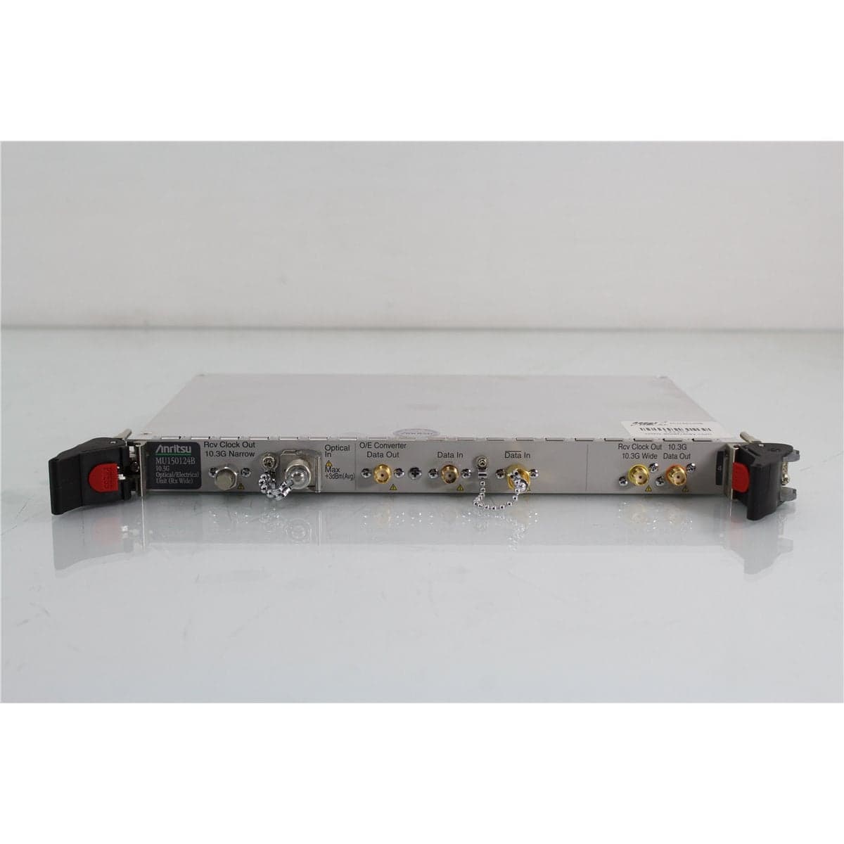
Anritsu · MU150124B
Anritsu MU150124B 10.3G Optical/Electrical Receiver Unit with Wide and Narrow Clock Recovery
$3,992.00
Price in USD.
- Condition
- Used
- Availability
- In stock
- Model
- MU150124B
- Manufacturer
- Anritsu
- Category
- O-E Receivers & E-O Transmitters
Description
Anritsu MU150124B 10.3G Optical/Electrical Receiver Unit
The Anritsu MU150124B is a plug-in optical/electrical receiver unit designed for compatible Anritsu MP1590B and MP1591A Network Performance Testers. It converts high-speed optical NRZ data into an electrical NRZ signal and recovers a clock from optical or electrical input data for jitter measurements and network performance testing.
The module operates with bit rates of 9953.28 Mbit/s, 10312.5 Mbit/s, and 10709.32 Mbit/s. Its optical receiver covers wavelengths from 1260 nm to 1610 nm, supporting high-speed optical testing in the 1310 nm and 1550 nm transmission regions.
The MU150124B provides optical and electrical input capabilities, an O/E converter output, a standard electrical data output, and separate narrowband and wideband recovered clock outputs. These functions support optical receiver testing, signal conversion, loopback measurements, clock recovery, and jitter analysis within a compatible Anritsu test platform.
Features and Benefits of the Anritsu MU150124B
- 10.3G optical-to-electrical conversion: Converts a 10.3125 Gbit/s optical NRZ signal into an electrical NRZ output.
- Three supported bit rates: Operates at 9953.28, 10312.5, and 10709.32 Mbit/s with a tolerance of ±100 ppm.
- Wide optical wavelength coverage: Accepts optical signals from 1260 nm to 1610 nm.
- Optical receiver sensitivity: Supports optical input levels from -14 dBm to 0 dBm under the specified conditions.
- Single-mode optical interface: Uses a replaceable FC/PC connector interface for compatible single-mode fiber.
- Narrowband clock recovery: Provides a 10.3125 GHz recovered clock output with a nominal 4 MHz bandwidth.
- Wideband clock recovery: Provides a second 10.3125 GHz recovered clock output with a nominal 80 MHz bandwidth.
- Electrical signal input: Accepts differential or single-ended electrical NRZ data for clock recovery and jitter measurements.
- Optical power measurement: Measures input optical power from -20 dBm to +2 dBm.
- Adjustable decision threshold: Provides ±50 mV of threshold adjustment in 1 mV increments.
- SMA electrical interfaces: Uses 50-ohm, AC-coupled SMA connectors for high-speed data and clock connections.
- Modular test-system integration: Installs in compatible MP1590B and MP1591A Network Performance Tester mainframes.
Optical-to-Electrical Signal Conversion
The MU150124B receives a digitally modulated optical signal and converts the optical input into an electrical NRZ data signal. This function enables compatible electrical error detectors, jitter analyzers, and network performance test equipment to evaluate signals originating from optical transmitters, transceivers, fiber links, and communication systems.
The optical receiver supports 9.95328, 10.3125, and 10.70932 Gbit/s signals. The O/E converter data output is available through a 50-ohm, AC-coupled SMA connector.
With an optical input level from -12 dBm to -10 dBm, the O/E converter output level is specified at 0.35 V peak-to-peak ±0.15 V. Actual output depends on optical input power, wavelength, signal quality, extinction ratio, and system configuration.
1260 nm to 1610 nm Optical Receiver
The optical receiver covers wavelengths from 1260 nm to 1610 nm. This range includes the primary 1310 nm and 1550 nm windows used by many high-speed single-mode optical communication systems.
The specified optical input range is -14 dBm to 0 dBm. The design-assurance maximum input is +3 dBm average. The +3 dBm value is an absolute input limit rather than the recommended level for normal measurement operation.
The optical input provides return loss of at least 27 dB and uses a replaceable FC/PC interface for single-mode fiber. The loss-of-signal detection level is -23 dBm or less.
Narrowband and Wideband Clock Recovery
The MU150124B provides separate narrowband and wideband recovered clock outputs for 10.3125 Gbit/s signals. Both outputs provide a nominal frequency of 10312.5 MHz with a tolerance of ±100 ppm.
The narrowband clock output has a nominal jitter transfer bandwidth of 4 MHz. The wideband clock output has a nominal jitter transfer bandwidth of 80 MHz. These two paths allow the measurement system to evaluate timing and jitter behavior with different clock recovery characteristics.
Each recovered clock output provides 0.8 V peak-to-peak ±0.25 V through an SMA 50-ohm, AC-coupled interface.
Electrical Data Input
The Anritsu MU150124B can recover clock signals from electrical NRZ data in addition to its optical receiver input. The electrical input supports bit rates of 9953.28, 10312.5, and 10709.32 Mbit/s.
Differential input operation supports an amplitude from 50 mVpp to 550 mVpp on each side of the signal pair. Single-ended operation supports amplitudes from 100 mVpp to 550 mVpp.
The electrical inputs use SMA 50-ohm AC-coupled interfaces. Skew tolerance is specified at ±15 ps under the documented loopback measurement conditions.
10.3G Electrical Data Output
The module provides an electrical NRZ data output for supported 10G, 10.3G, and 10.7G bit rates. The high output level is specified from -0.2 V to 0 V, while the low output level is specified from -1.25 V to -0.75 V.
The electrical data output uses a 50-ohm AC-coupled SMA connector. Suitable high-frequency cables, terminations, and adapters should be used to maintain signal integrity at data rates above 10 Gbit/s.
Optical Power Measurement
The MU150124B includes an optical input power measurement function with a range from -20 dBm to +2 dBm. This function allows the user to monitor the optical level applied to the receiver directly through the compatible mainframe system.
Measurement accuracy is specified at ±0.5 dB from -10 dBm to -1.1 dBm. Accuracy is specified at ±1.0 dB from -20 dBm to -10.1 dBm and from -1 dBm to +2 dBm.
The system provides an over-range indication for levels at or above +2 dBm and an under-range indication for levels at or below -20 dBm.
Adjustable Input Threshold
The data input decision threshold can be adjusted over a ±50 mV range in 1 mV steps. This allows the user to control the decision point when testing single-ended electrical signals or signals converted through the optical receiver.
Threshold adjustment is useful when evaluating signals with DC offset, asymmetric levels, degraded eye openings, or other conditions requiring a controlled receiver decision level.
Jitter Measurement Applications
The MU150124B is designed to support optical and electrical jitter measurements at 10.3125 Gbit/s. Its recovered clock outputs provide narrowband and wideband clock paths for different jitter-analysis requirements.
Documented system testing uses compatible Anritsu transmitter, receiver, pulse-pattern, error-detection, and jitter modules. Measurement configurations may use 1310 nm or 1550 nm optical signals, PRBS23 or PRBS31 patterns, and an extinction ratio of at least 8.2 dB.
The exact test functions available depend on the compatible mainframe, installed modules, system options, software revision, and interconnecting cables.
Typical Applications
- 10.3125 Gbit/s optical receiver testing
- 10G, 10.3G, and 10.7G NRZ signal analysis
- Optical-to-electrical signal conversion
- Optical and electrical jitter measurements
- Recovered clock generation
- 1310 nm and 1550 nm optical link testing
- Optical transmitter and receiver evaluation
- Bit error ratio test-system integration
- Network performance testing
- Optical transceiver development
- Production and quality-control testing
- Telecommunications laboratory applications
Product Overview
| Brand | Anritsu |
| Model | MU150124B |
| Product Category | 10.3G Optical/Electrical Receiver Unit |
| Receiver Description | 10.3G Optical/Electrical Unit, Rx Wide |
| Supported Bit Rates | 9953.28, 10312.5, and 10709.32 Mbit/s |
| Optical Wavelength Range | 1260 nm to 1610 nm |
| Optical Input Range | -14 dBm to 0 dBm |
| Optical Connector | Replaceable FC/PC single-mode interface |
| Recovered Clock | 10312.5 MHz narrowband and wideband outputs |
| Compatible Mainframes | Anritsu MP1590B and MP1591A |
| Primary Application | 10.3G optical-to-electrical conversion, clock recovery, and jitter measurement |
Optical Input Specifications
| Specification | Details |
| Supported Bit Rates | 9953.28, 10312.5, and 10709.32 Mbit/s, each ±100 ppm |
| Optical Wavelength Range | 1260 nm to 1610 nm |
| Optical Input Range | -14 dBm to 0 dBm |
| Maximum Optical Input | +3 dBm average, design assurance |
| Signal Format | NRZ |
| Optical Return Loss | 27 dB or more |
| Optical Interface | FC/PC for single-mode fiber |
| Loss-of-Signal Detection Level | -23 dBm or less |
Optical-to-Electrical Output Specifications
| Specification | Details |
| Supported Bit Rates | 9953.28, 10312.5, and 10709.32 Mbit/s, each ±100 ppm |
| Output Level | 0.35 Vp-p ±0.15 V with an optical input from -12 dBm to -10 dBm |
| Output Interface | SMA, 50 ohms, AC coupled |
Electrical Data Output Specifications
| Specification | Details |
| Supported Bit Rates | 9953.28, 10312.5, and 10709.32 Mbit/s, each ±100 ppm |
| Signal Format | NRZ |
| High Output Level | -0.2 V to 0 V |
| Low Output Level | -1.25 V to -0.75 V |
| Output Interface | SMA, 50 ohms, AC coupled |
Recovered Clock Specifications
| Specification | Narrow Output | Wide Output |
| Recovered Clock Frequency | 10312.5 MHz ±100 ppm | 10312.5 MHz ±100 ppm |
| Output Level | 0.8 Vp-p ±0.25 V | 0.8 Vp-p ±0.25 V |
| Nominal Bandwidth | 4 MHz | 80 MHz |
| Output Interface | SMA, 50 ohms, AC coupled | SMA, 50 ohms, AC coupled |
Electrical Input Specifications
| Specification | Details |
| Supported Bit Rates | 9953.28, 10312.5, and 10709.32 Mbit/s, each ±100 ppm |
| Differential Input Level | 50 mVpp to 550 mVpp per side |
| Single-Ended Input Level | 100 mVpp to 550 mVpp |
| Skew Tolerance | ±15 ps under the documented test conditions |
| Input Interface | SMA, 50 ohms, AC coupled |
Optical Power Measurement Specifications
| Specification | Details |
| Measurement Range | -20 dBm to +2 dBm |
| Accuracy from -10 dBm to -1.1 dBm | ±0.5 dB or less |
| Accuracy from -20 dBm to -10.1 dBm | ±1.0 dB or less |
| Accuracy from -1 dBm to +2 dBm | ±1.0 dB or less |
| Upper Range Indication | Greater than +2 dBm |
| Lower Range Indication | Less than -20 dBm |
| Threshold Adjustment Range | ±50 mV |
| Threshold Adjustment Resolution | 1 mV |
Mechanical and Environmental Specifications
| Specification | Details |
| Operating Temperature | 0 °C to 40 °C, except for specified jitter measurements |
| Jitter Measurement Temperature | 10 °C to 40 °C |
| Storage Temperature | -20 °C to 60 °C |
| Dimensions | 234 mm wide x 21 mm high x 175 mm deep, excluding protrusions |
| Mass | 1.5 kg or less |
System Requirements and Compatibility
The MU150124B requires a compatible Anritsu MP1590B or MP1591A Network Performance Tester. The mainframe supplies power, system controls, configuration functions, display capabilities, and software support.
Using the 10.3G bit rate with an MU150100A requires Option 08. A compatible MU150125A Jitter Unit requires Option 06 for the applicable 10.3G measurements.
Optical testing may also require a compatible MU150121A or MU150121B transmitter module. Externally modulated optical applications may use a compatible MU150134A unit.
Mainframe compatibility, installed firmware, software revision, module options, RF cables, optical cables, and selected test application should be confirmed before integration.
Comprehensive Functional and Performance Testing
The Anritsu MU150124B receives comprehensive functional and performance testing before shipment. Testing may include installation in a compatible mainframe, module recognition, optical input detection, optical power measurement, O/E conversion, electrical input operation, threshold adjustment, and data output verification.
When suitable 10G test equipment is available, testing may include operation at supported bit rates, recovered clock frequency, narrowband and wideband clock output, optical receiver sensitivity, loss-of-signal response, loopback operation, and jitter-related functions.
The replaceable FC/PC optical interface may be inspected for contamination, physical damage, worn alignment components, or incompatible connector use. The SMA connectors may be checked for damaged threads, bent center contacts, loose mounting, and excessive wear.
The exact testing scope depends on the available mainframe, transmitter, pattern generator, error detector, jitter unit, optical source, optical attenuator, high-frequency cables, and supporting measurement equipment.
Buyer Considerations
Buyers should confirm that the module is the MU150124B 10.3G Optical/Electrical Unit identified as the Rx Wide model. Other Anritsu MU15012x modules provide different transmitter, receiver, bandwidth, and bit-rate functions.
The MU150124B is a plug-in module and should not be considered a standalone optical receiver. A compatible mainframe and additional test modules may be required to create a complete measurement system.
Only the module, optical cable, 10 dB attenuator, semirigid cables, mainframe, operating software, manual, and accessories specifically identified in the individual product listing should be considered included.
Why Buy from AssetRelay?
AssetRelay supplies professional equipment and product solutions for fiber optic, telecom, laboratory, production, electronic test, RF/microwave, photonics, inspection, cleaning, and high-speed digital communications applications. The Anritsu MU150124B provides optical-to-electrical conversion and recovered clock capability for engineers, telecommunications laboratories, manufacturers, service organizations, and production facilities.
Buyers should review the product photographs, physical condition, optical interface, SMA connectors, supported bit rates, mainframe compatibility, optical receiver operation, recovered clock outputs, included accessories, and testing information before purchase.