
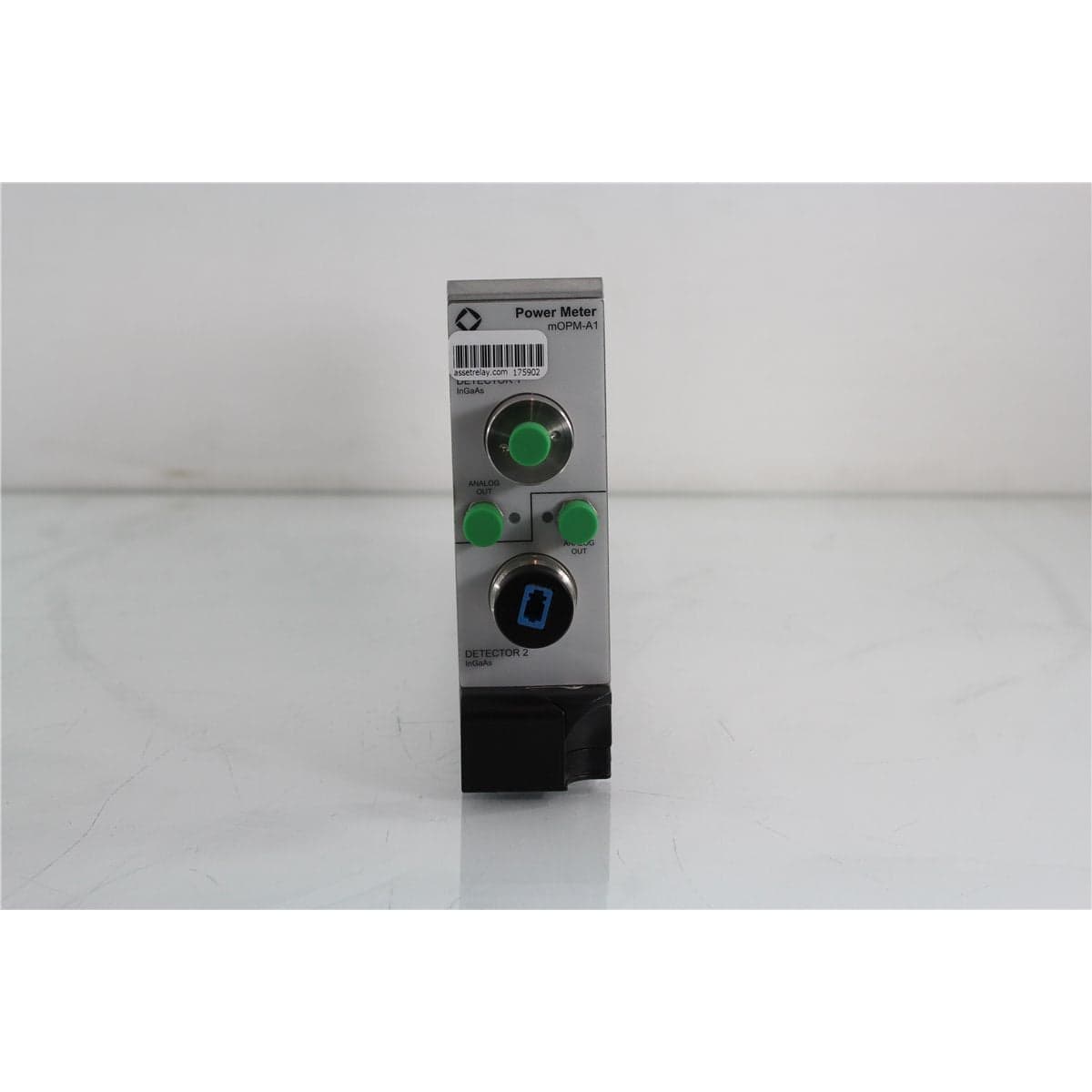
JDS · MOPM-A1110
JDSU mOPM-A1110 Dual-Channel InGaAs MAP Optical Power Meter Module
$3,040.00
Price in USD.
- Condition
- Used
- Availability
- In stock
- Model
- MOPM-A1110
- Manufacturer
- JDS
- Category
- Multi Channel Power Meters
Description
JDSU mOPM-A1110 Dual-Channel InGaAs MAP Optical Power Meter Module
The JDSU mOPM-A1110 is a dual-channel optical power meter module designed for the JDSU MAP-200 Multiple Application Platform. This configuration contains a 3 mm InGaAs detector on Channel 1 and a second 3 mm InGaAs detector on Channel 2, enabling two optical signals to be measured within one modular instrument.
Each detector covers wavelengths from 800 nm to 1650 nm and measures continuous-wave optical power from -80 dBm to +10 dBm. The module supports compatible single-mode and multimode fibers with numerical aperture up to 0.27 and a maximum single-fiber core diameter of 62.5 µm.
The mOPM-A1110 combines high accuracy, high linearity, low polarization-dependent loss, selectable averaging, and analog monitoring outputs. These capabilities make it suitable for DWDM channel measurements, optical amplifier characterization, bit error rate testing, precise optical power control, receiver testing, transmitter evaluation, laboratory research, and automated production systems.
Features and Benefits of the JDSU mOPM-A1110
The JDSU mOPM-A1110 provides two optical power measurement channels for engineers, laboratories, production facilities, and service organizations working with fiber optic and photonic systems.
- Dual-channel configuration: Includes a 3 mm InGaAs optical detector on both Channel 1 and Channel 2.
- Wide wavelength coverage: Measures optical power from 800 nm to 1650 nm.
- Broad power range: Measures continuous-wave optical signals from -80 dBm to +10 dBm.
- Single-mode and multimode support: Accepts compatible SMF and MMF with numerical aperture up to 0.27.
- Low polarization-dependent loss: Provides polarization relative uncertainty of ±0.01 dB under the specified conditions.
- High linearity: Provides linearity of ±0.025 dB from -65 dBm to +10 dBm across the specified wavelength range.
- Fast measurement capability: Supports averaging times from 100 µs to 5 seconds.
- Low optical noise: Provides peak-to-peak noise below 5 pW under the specified measurement conditions.
- Analog outputs: Provides 0 V to 2 V analog electrical outputs for compatible monitoring and acquisition equipment.
- Interchangeable detector adapters: Supports JDSU AC100 Series adapters for multiple optical connector formats and bare fiber measurement.
- MAP-200 automation: Supports automated testing through compatible LXI interfaces and IVI drivers.
- Optional high-power measurement: Supports measurements up to +33 dBm or 2 W when used with the optional AC330 integrating sphere.
Dual-Channel Optical Power Measurement
The MOPM-A1110 product code identifies a dual-detector configuration with 3 mm InGaAs detectors installed on both channels. This arrangement allows two optical signals to be connected and measured through the same MAP module.
Dual-channel operation can be useful when comparing input and output power, monitoring two DWDM paths, evaluating optical amplifier gain, measuring two component ports, or observing source stability while simultaneously measuring a device under test.
The exact measurement sequence, channel synchronization, data recording, and automation functions depend on the compatible MAP chassis, controller, firmware, software, and test configuration.
800 nm to 1650 nm Wavelength Range
Each InGaAs detector covers wavelengths from 800 nm to 1650 nm. This broad range supports near-infrared and telecom measurements, including applications around 850 nm, 1310 nm, 1490 nm, 1550 nm, and other wavelengths within the supported range.
Reference-condition uncertainty is specified at ±2.5% from 1200 nm to 1550 nm and ±4.0% from 800 nm to below 1200 nm. Total uncertainty is specified at ±4.5% ±5 pW from 800 nm to 1630 nm under the defined operating conditions.
For measurements above 1600 nm at temperatures above 35 °C, an additional 1% uncertainty applies. Measurement results also depend on source spectral width, fiber type, connector adapter, numerical aperture, optical power, calibration age, and environmental conditions.
Wide Optical Power Range
The mOPM-A1110 measures continuous-wave optical power from -80 dBm to +10 dBm. This range supports low-level optical measurements and higher-power source or component testing without requiring separate standard detectors for different signal levels.
The detector provides linearity of ±0.025 dB from -65 dBm to +10 dBm over wavelengths from 1520 nm to 1570 nm at an ambient temperature of 23 °C ±5 °C. For optical power between -30 dBm and +3 dBm, linearity is better than ±0.02 dB under the specified conditions.
When optical power exceeds the standard detector range, the optional AC330 integrating sphere can extend the maximum measurement capability to +33 dBm or 2 W. The integrating sphere introduces nominal attenuation and has separate wavelength-flatness, return-loss, uncertainty, and polarization-dependent-loss specifications.
Selectable Averaging and High-Speed Measurement
The module supports averaging times from 100 µs to 5 seconds. Short averaging times can support rapid measurements in production systems, alignment procedures, switching tests, and automated optical workflows.
Longer averaging times can be selected when improved stability is needed for low-level measurements. The appropriate averaging setting depends on signal level, source stability, required acquisition speed, noise performance, and the test procedure.
Peak-to-peak noise is specified below 5 pW with a one-second averaging time, a 300-second observation period, a wavelength of 1550 nm, and an ambient temperature of 23 °C ±5 °C.
Interchangeable Detector Adapters
The 3 mm InGaAs detector heads are designed for use with JDSU AC100 Series interchangeable adapters. This adapter system allows the optical interface to be configured for different connector formats or bare fiber measurements.
The mOPM-A1110 is supplied in its original configuration with one detector cap and one FC detector adapter per detector. For an individual used module, buyers should confirm the adapters and caps actually included in the product listing.
- AC100: Detector cap
- AC101: FC detector adapter
- AC102: ST detector adapter
- AC103: SC detector adapter
- AC112: MT ribbon cable adapter
- AC114: MU detector adapter
- AC115: E2000 detector adapter
- AC120: Magnetic fiber holder requiring the AC121 plug
- AC121: Single bare fiber plug requiring the AC120 holder
- AC330: +33 dBm integrating sphere
Bare Fiber Measurement Capability
The optional AC120 magnetic fiber holder and AC121 single bare fiber plug allow compatible bare fibers to be positioned at the detector. This capability is useful for laboratories, assembly operations, component production, and research applications where a connectorized fiber is unavailable or undesirable.
Bare fiber measurements require careful fiber preparation, positioning, cleaning, and handling. The fiber end should be properly cleaved and aligned with the detector to support repeatable coupling.
The bare fiber holder and plug should not be assumed to be included unless specifically identified in the product listing.
Typical Applications
The JDSU mOPM-A1110 Dual-Channel Optical Power Meter is suitable for professional applications such as:
- Dual-channel optical power measurement
- DWDM channel measurements
- Optical amplifier gain characterization
- Bit error rate test systems
- Precise optical power control
- Receiver and transmitter testing
- Single-mode and multimode fiber measurements
- Optical component insertion-loss testing
- Source stability monitoring
- Bare fiber measurements with compatible accessories
- Laboratory research and development
- Automated production and manufacturing tests
Product Overview
| Brand | JDSU / JDS Uniphase |
| Model | mOPM-A1110 |
| Product Family | MAP Optical Power Meter, mOPM-A1 Series |
| Product Category | Dual-Channel Optical Power Meter Module |
| Channel 1 Detector | 3 mm InGaAs |
| Channel 2 Detector | 3 mm InGaAs |
| Compatible Platform | JDSU MAP-200 Multiple Application Platform |
| Standard Detector Adapter | FC adapter for each detector in the original configuration |
| Primary Application | Dual-channel optical power measurement from 800 nm to 1650 nm |
| Suitable For | Fiber optic laboratories, DWDM testing, amplifier characterization, production testing, and automated optical measurement systems |
Optical Specifications
| Specification | JDSU mOPM-A1110 Details |
| Detector Configuration | Dual 3 mm InGaAs detectors |
| Wavelength Range | 800 nm to 1650 nm |
| Continuous-Wave Power Range | -80 dBm to +10 dBm |
| Applicable Fiber Types | Single-mode and multimode fiber |
| Maximum Fiber Numerical Aperture | 0.27 |
| Maximum Single-Fiber Core Diameter | 62.5 µm with numerical aperture up to 0.27 |
| Reference Uncertainty, 1200–1550 nm | ±2.5% |
| Reference Uncertainty, 800–1200 nm | ±4.0% |
| Total Uncertainty, 800–1630 nm | ±4.5% ±5 pW |
| Polarization Relative Uncertainty | ±0.01 dB |
| Spectral Ripple | ±0.005 dB |
| Linearity, 1520–1570 nm | ±0.025 dB from -65 dBm to +10 dBm |
| Linearity, +3 to -30 dBm | Better than ±0.02 dB |
| Return Loss | Greater than 55 dB |
| Peak-to-Peak Noise | Less than 5 pW |
| Averaging Time | 100 µs to 5 seconds |
| Analog Output | 0 V to 2 V |
Reference and Operating Conditions
The ±2.5% reference uncertainty from 1200 nm to 1550 nm is specified using SMF-28 fiber, an ambient temperature of 23 °C ±3 °C, a source spectral width below 1 nm, and 100 µW or -10 dBm of optical power at the detector.
Total uncertainty applies with fiber numerical aperture up to 0.27 and within the specified temperature, humidity, and optical power ranges. An additional 1% applies when an FC/APC connector with a numerical aperture of 0.27 is used.
For wavelengths above 1600 nm and temperatures above 35 °C, an additional 1% uncertainty applies. Return loss is specified at 1310 nm and 1550 nm using an eight-degree angled connector at an ambient temperature of 23 °C ±5 °C.
Optional AC330 High-Power Integrating Sphere
The optional JDSU AC330 integrating sphere allows a compatible InGaAs detector channel to measure continuous-wave optical power up to +33 dBm or 2 W. It attaches to the front of the module and introduces nominal attenuation before the optical signal reaches the detector.
| AC330 Specification | Details |
| Reference Attenuation | -30.7 dB ±0.8 dB |
| Spectral Range | 800 nm to 1650 nm |
| Wavelength Flatness | Less than ±1.5 dB |
| Return Loss | Greater than 65 dB typical |
| Relative Uncertainty | Less than ±0.05 dB |
| Residual Polarization-Dependent Loss | Less than 0.005 dB |
| Maximum Optical Power | +33 dBm or 2 W continuous wave |
| Operating Temperature | 10 °C to 40 °C |
The AC330 integrating sphere is optional and should not be assumed to be included unless specifically identified in the product listing.
Physical and Environmental Specifications
| Specification | Details |
| Operating Temperature | 5 °C to 40 °C |
| Humidity | Non-condensing |
| Dimensions | 4.06 cm wide x 13.26 cm high x 37.03 cm deep |
| Dimensions, Imperial | 1.6 inches wide x 5.22 inches high x 14.58 inches deep |
| Weight | 1.2 kg (2.65 lb) |
| Warm-Up Time | 20 minutes |
| Recommended Recalibration Period | One year |
MAP-200 Platform Integration
The JDSU mOPM-A1110 requires a compatible MAP-200 chassis for power, display, local control, channel configuration, wavelength entry, averaging selection, data acquisition, and automation access. The module does not function as a standalone optical power meter.
The MAP-200 platform supports Ethernet-based LXI connectivity and interchangeable virtual instrument drivers for automated optical testing. Depending on the system configuration, the dual-channel power meter can be coordinated with tunable lasers, optical switches, variable optical attenuators, and other compatible MAP modules.
Automated systems can use the mOPM-A1110 for high-density DWDM measurements, with support for applications involving up to 128 channels or controller addresses when the complete system is configured appropriately.
Measurement Preparation and Detector Care
The mOPM-A1110 should complete its 20-minute warm-up period before precision measurements. Each detector should be zeroed and configured for the correct wavelength, averaging time, and measurement range before optical power is applied.
Detector adapters, optical connectors, and fiber end faces should be inspected and cleaned before connection. Contamination can introduce loss, instability, reflection, and measurement errors.
When changing detector adapters, users should consider the effect on measurement accuracy. The original calibration is associated with the detector and specified adapter configuration, and recalibration is recommended when the optical adapter is changed for applications requiring specified accuracy.
Calibration and Testing Before Shipment
When calibration is technically applicable and supported, the JDSU mOPM-A1110 is calibrated before shipment. The calibration process may include both optical channels and verification of wavelength response, optical power accuracy, linearity, noise, analog output, averaging functions, channel operation, and supported detector adapters.
Following successful calibration, the module may include a calibration label, calibration certificate, and related calibration data, depending on the equipment configuration and calibration service. The specified recalibration period for the mOPM-A1 InGaAs optical power meter is one year.
If formal calibration is unavailable or not applicable to the specific module configuration, the unit receives comprehensive functional and performance testing. This process may include compatible-chassis recognition, optical response on both channels, detector zeroing, channel selection, optical power measurement, analog output, averaging controls, connector inspection, and automated interface operation.
This testing helps verify that the equipment operates correctly and that its available functions have been evaluated before it is released for shipment. The exact calibration scope, documentation, detector adapters, test data, and service records should be confirmed before purchase when these items are required for laboratory, production, regulatory, or quality-management applications.
Buyer Considerations
The JDSU mOPM-A1110 is specifically the dual 3 mm InGaAs detector configuration. Buyers should confirm that both Channel 1 and Channel 2 detectors are present and operational and that the included detector adapters match the intended connector types.
The mOPM-A1110 should not be confused with the mOPM-A1100 single-channel InGaAs module, the mOPM-A1200 single-channel 10 mm germanium module, or the mOPM-A1120 mixed InGaAs and germanium configuration.
Buyers should review the detector surfaces, adapter condition, analog outputs, MAP chassis compatibility, physical condition, calibration status, and included accessories. A compatible MAP-200 chassis, optical patch cables, additional detector adapters, bare fiber accessories, integrating sphere, software, and automation equipment may be required separately.
Why Buy from AssetRelay?
AssetRelay supplies professional equipment and product solutions for fiber optic, telecom, laboratory, production, inspection, cleaning, RF/microwave, electronic test, and photonics applications. The JDSU mOPM-A1110 is listed to help engineers, laboratory personnel, production facilities, procurement teams, and service organizations source dual-channel optical power measurement equipment for professional test systems.
Buyers should review the available product photographs, physical condition, detector and adapter condition, included accessories, calibration information, and MAP-200 compatibility before purchase. Confirming these details helps ensure that the module matches the intended wavelength range, optical power range, fiber type, connector format, measurement speed, and automated test workflow.
Only accessories specifically identified in the product listing should be considered included. The MAP-200 chassis, optical patch cables, detector adapters, bare fiber holder, integrating sphere, software, and automation accessories may be required separately.