
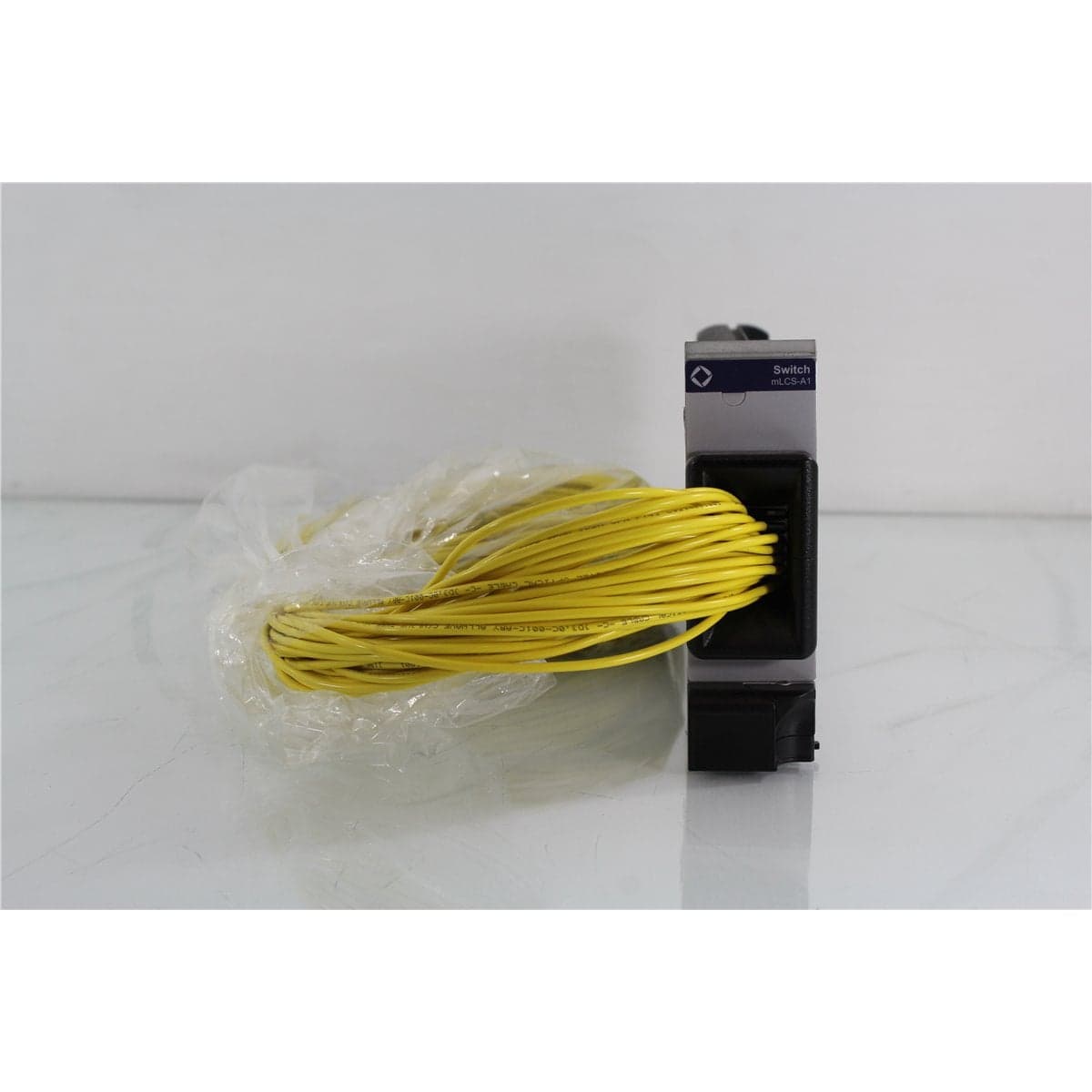
JDS · MLCS-A1216P
JDSU mLCS-A1216P Dual Independent 1x16 Large Channel Count Optical Switch Module
$3,192.00
Price in USD.
- Condition
- Used
- Availability
- In stock · 2 available
- Model
- MLCS-A1216P
- Manufacturer
- JDS
- Category
- Optical Switches 9-125 2xN
Description
JDSU mLCS-A1216P Dual Independent 1x16 Large Channel Count Optical Switch Module
The JDSU mLCS-A1216P is a dual independent 1x16 optical switch module designed for the JDSU MAP-200 Multiple Application Platform. It combines two separate optical switches in one compact plug-in cassette, with each switch routing one common input to any one of 16 output channels.
The two switch sections operate independently, enabling separate optical paths to be controlled within the same module. This configuration supports automated testing of multiple components, dual-path measurement systems, parallel optical workflows, and applications that require two separately controlled banks of optical channels.
The mLCS-A1 family uses JDSU expanded-beam and alignment technologies to provide low insertion loss, high return loss, low polarization-dependent loss in supported single-mode configurations, and repeatable channel selection. The switch helps improve test throughput by reducing manual patch-cord changes and minimizing uncertainty caused by repeated connector mating.
The P suffix identifies a pigtail-based switch configuration. Fiber type and connector style are separate ordering options and should be verified from the complete module label, installed pigtails, and product photographs. Available family options include 9/125 µm single-mode, 50/125 µm multimode, and 62.5/125 µm multimode fiber with compatible FC or SC connector configurations.
Features and Benefits of the JDSU mLCS-A1216P
- Dual independent switching: Integrates two independently controlled 1x16 optical switches within one module.
- Thirty-two selectable outputs: Provides two banks of 16 output channels for automated optical routing.
- Pigtail configuration: Uses optical pigtails rather than front-panel bulkhead connections.
- Expanded-beam technology: Supports stable optical alignment, low path loss, and repeatable switching.
- Fast optical switching: Provides a documented switching time of 25 ms for the first channel and 15 ms for each additional channel.
- High switching repeatability: Supports consistent optical routing across repeated automated test sequences.
- Long operating life: Rated for more than 100 million switching cycles.
- High optical input capacity: Supports maximum optical input power up to 300 mW under the documented conditions.
- MAP-200 integration: Installs in a compatible JDSU MAP chassis for power, control, and automation.
- Reduced connector handling: Minimizes repeated manual reconnection of test equipment and devices under test.
- Flexible fiber options: The product family supports single-mode and multimode fiber configurations.
- Automated test support: Suitable for DWDM testing, amplifier characterization, BER testing, and multi-device component evaluation.
Dual Independent 1x16 Architecture
The mLCS-A1216P contains two distinct 1x16 switch sections. Each section has one common optical input and 16 individually selectable outputs. The two switches can be configured for separate optical paths and controlled independently through the compatible MAP platform.
This arrangement is useful for test systems that require simultaneous source and receiver routing, separate input and output switching, comparative measurements, or two independent groups of devices under test.
Unlike a single 1x32 switch, the mLCS-A1216P does not provide one common input that can access all 32 outputs. The module provides two independent common inputs, each associated with its own bank of 16 output channels.
Automated Optical Signal Routing
The mLCS-A1216P allows test software or the compatible MAP platform to select optical paths without requiring an operator to move patch cords manually. This improves throughput when multiple components or channels must be measured using the same optical source and test equipment.
Automated routing also reduces connector wear and helps preserve a controlled test setup. Repeated manual mating can introduce contamination, connection variability, and differences in insertion loss that affect measurement repeatability.
The switch can be coordinated with tunable lasers, fixed-wavelength sources, optical attenuators, power meters, spectrum analyzers, bit error rate testers, amplifiers, and other compatible optical test equipment.
Expanded-Beam Switching Technology
The JDSU mLCS-A1 platform is based on expanded-beam optical alignment technology. The selected optical channel is positioned using a controlled mechanical alignment system that couples the input signal into the required output fiber.
This design supports low insertion loss and repeatable channel selection while avoiding frequent physical remating of external optical connectors. The technology is suited to automated environments where the switch may complete a large number of routing operations during its service life.
Fast Switching Performance
The documented switching time is 25 ms for the first channel and 15 ms for each additional channel traversed. Total switching time depends on the distance between the current and requested positions.
Fast switching supports automated production testing, multi-channel component characterization, signal monitoring, and other applications where numerous optical paths must be selected during one test sequence.
Measurement software should allow sufficient time for the selected channel to settle before acquiring data from the connected power meter, receiver, or analyzer.
Optical Performance for 1x16 Configurations
The mLCS-A1216P has 16 outputs per independent switch, placing it within the mLCS-A1 performance category for configurations containing 25 or fewer output channels.
For a 9/125 µm single-mode configuration, insertion loss is specified at 0.5 dB typical and 0.7 dB maximum, excluding external connectors. Typical polarization-dependent loss is 0.02 dB, with a documented maximum of 0.04 dB.
Single-mode return loss is specified at 62 dB typical and 57 dB minimum. Sequential switching repeatability is ±0.005 dB typical and ±0.01 dB maximum. Random switching repeatability is ±0.01 dB typical and ±0.05 dB maximum.
For supported 50/125 µm and 62.5/125 µm multimode configurations, insertion loss is specified at 0.4 dB typical and 0.6 dB maximum. Fiber-specific performance should be applied only after the installed fiber option has been confirmed.
Fiber and Connector Options
Fiber type and connector configuration are selected separately from the mLCS-A1216P base model. Supported fiber options include 9/125 µm single-mode, 50/125 µm multimode, and 62.5/125 µm multimode fiber.
Available connector options include FC/PC, FC/APC, SC/PC, and SC/APC, subject to fiber compatibility. Angled-contact FC/APC and SC/APC options are specified only for the supported 9/125 µm single-mode configuration.
The installed fiber and connector option should be confirmed from the individual module. Connector polish, pigtail length, labeling, and optical path assignments should not be assumed from the base model number alone.
Typical Applications
- DWDM channel testing
- Optical amplifier characterization
- Bit error rate testing
- Automated optical signal routing
- Multi-device fiber optic component testing
- Optical source distribution
- Receiver and detector channel selection
- Insertion-loss measurement systems
- Optical power monitoring
- Production and qualification testing
- Telecommunications laboratory systems
- Photonics research and development
Product Overview
| Brand | JDSU |
| Model | mLCS-A1216P |
| Product Family | mLCS-A1 MAP Large Channel Count Switch |
| Product Category | Modular Programmable Optical Switch |
| Switch Configuration | Dual independent 1x16 |
| Common Inputs | Two, one per independent switch |
| Outputs | Two banks of 16 outputs |
| Optical Connection Format | Pigtails |
| Compatible Platform | JDSU MAP-200 Multiple Application Platform |
| Primary Application | Automated dual-path optical signal routing and component testing |
Single-Mode Optical Specifications
| Specification | Typical | Maximum or Minimum |
| Wavelength Range | 1270 nm to 1670 nm | |
| Insertion Loss | 0.5 dB | 0.7 dB maximum |
| Polarization-Dependent Loss | 0.02 dB | 0.04 dB maximum |
| Return Loss | 62 dB | 57 dB minimum |
| Insertion-Loss Stability | ±0.02 dB | ±0.025 dB maximum |
| Sequential Switching Repeatability | ±0.005 dB | ±0.01 dB maximum |
| Random Switching Repeatability | ±0.01 dB | ±0.05 dB maximum |
| Crosstalk | -80 dB | Maximum limit not specified |
Multimode Optical Specifications
| Specification | Typical | Maximum or Minimum |
| Supported Fiber Types | 50/125 µm or 62.5/125 µm multimode fiber | |
| Available Wavelength Ranges | 850 nm to 1350 nm or 750 nm to 940 nm, depending on configuration | |
| Insertion Loss | 0.4 dB | 0.6 dB maximum |
| Return Loss | 25 dB | 20 dB minimum |
| Insertion-Loss Stability | ±0.02 dB | ±0.025 dB maximum |
| Sequential Switching Repeatability | ±0.005 dB | ±0.01 dB maximum |
| Random Switching Repeatability | ±0.01 dB | ±0.05 dB maximum |
Switching and General Specifications
| Specification | Details |
| Switch Technology | Expanded-beam optical alignment |
| First-Channel Switching Time | 25 ms |
| Each Additional Channel | 15 ms |
| Maximum Optical Input Power | 300 mW |
| Switching Lifetime | More than 100 million cycles |
| Operating Temperature | -5 °C to 55 °C |
| Storage Temperature | -30 °C to 60 °C |
Physical Specifications
| Specification | Details |
| Width | 4.06 cm or 1.6 in |
| Height | 13.26 cm or 5.22 in |
| Depth | 37.03 cm or 14.58 in |
| Maximum Weight | Approximately 1.3 kg or 2.87 lb, varying with configuration |
| Connection Style | Optical pigtails |
Available Fiber and Connector Options
| Option Code | Description |
| M100 | 9/125 µm single-mode fiber |
| M101 | 50/125 µm multimode fiber |
| M102 | 62.5/125 µm multimode fiber |
| MFP | FC/PC connector configuration |
| MFA | FC/APC connector configuration for supported 9/125 µm single-mode fiber |
| MSC | SC/PC connector configuration |
| MSU | SC/APC connector configuration for supported 9/125 µm single-mode fiber |
MAP-200 Platform Requirements
The mLCS-A1216P requires a compatible JDSU MAP chassis. The host platform provides operating power, module recognition, switch-position control, local operation, and access to supported automation interfaces.
Chassis model, firmware revision, controller configuration, available slot capacity, and module compatibility should be confirmed before installation.
The switch cannot be operated as a standalone instrument. A MAP chassis, controller, optical patch cords, and control software are included only when specifically identified in the product listing.
Optical Connection and Setup Considerations
The input and output pigtails for both independent switch sections should be positively identified before the module is integrated into a test system. Port labels should be recorded so automated software selects the intended path.
The installed fiber type and connector polish must match the connected optical equipment. APC and non-angled physical-contact connectors should not be directly intermated.
All connector end faces should be inspected and cleaned before use. Optical pigtails should be protected from tight bends, tension, twisting, crushing, and mechanical stress at the module exit.
The module should be allowed to stabilize for one hour before measurements requiring the documented optical specifications are performed. External sources, detectors, and measurement instruments should also complete their recommended warm-up periods.
Comprehensive Functional and Performance Testing
The JDSU mLCS-A1216P receives comprehensive functional and performance testing before shipment. Evaluation may include installation in a compatible MAP chassis, module recognition, independent control of both switch sections, channel selection, input-to-output mapping, and repeated switching through both 16-channel banks.
Optical testing may include continuity, insertion-loss comparison, switching repeatability, path stability, crosstalk, and verification of representative channels using compatible sources, power meters, and reference cables.
The module connector, pigtails, optical connectors, strain relief, faceplate, retaining hardware, channel labels, and enclosure may be inspected for contamination, damage, excessive wear, or mechanical problems.
The exact testing scope depends on the installed fiber and connector options, available MAP chassis, accessible optical paths, source wavelengths, calibrated power meters, return-loss equipment, and requested channel coverage.
Buyer Considerations
Buyers should confirm the complete model as JDSU mLCS-A1216P. This model identifies two independent 1x16 switches with pigtail optical connections.
The fiber option, connector option, pigtail length, connector polish, port labeling, and MAP chassis compatibility should be verified from the individual module. These details are not fully identified by the mLCS-A1216P base model alone.
Only the switch module, MAP chassis, optical pigtails, patch cords, protective caps, software, network cables, manuals, calibration records, and accessories specifically identified in the product listing should be considered included.
Why Buy from AssetRelay?
AssetRelay supplies professional equipment and product solutions for fiber optics, telecom, laboratory, production, optical testing, photonics, laser control, electronic testing, RF/microwave, inspection, and technical research applications. The JDSU mLCS-A1216P provides automated dual-path optical routing for component manufacturers, telecommunications laboratories, amplifier developers, production facilities, system integrators, universities, and research organizations.
Buyers should review the product photographs, complete model and option labels, fiber type, connector interfaces, pigtail condition, MAP chassis compatibility, both 1x16 switch sections, channel mapping, functional test results, and included accessories before purchase.