
Siemens · X75
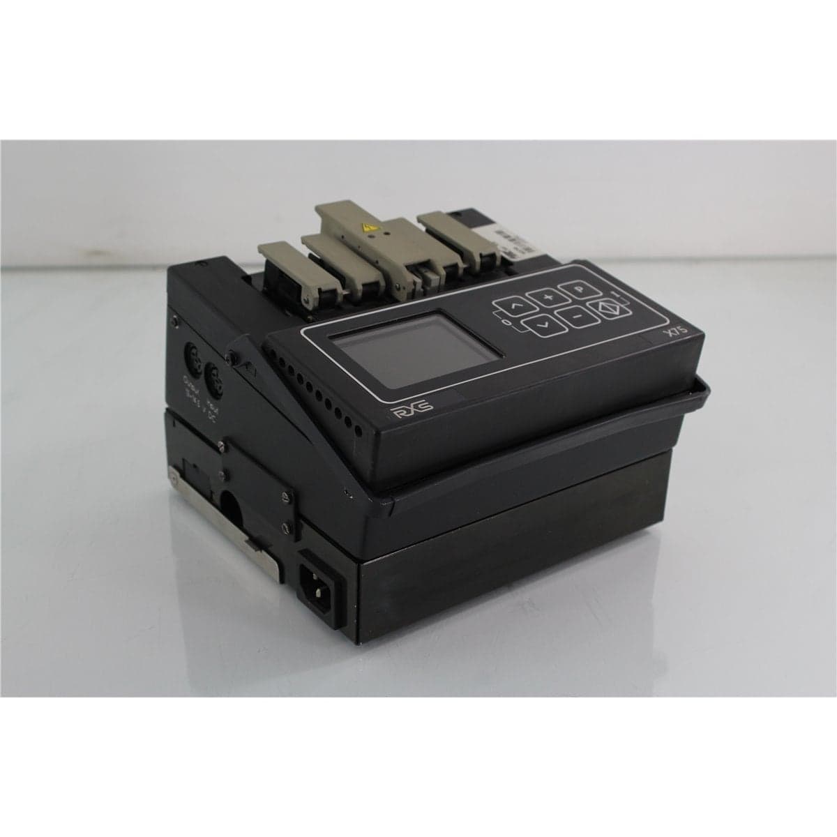
Siemens X75 Series 8000 Automatic Single-Mode and Multimode Fusion Splicer
$2,400.00
Price in USD.
- Condition
- Used
- Availability
- In stock
- Model
- X75
- Manufacturer
- Siemens
- Category
- Fusion Splicers
Description
Siemens X75 Series 8000 Automatic Fiber Fusion Splicer
The Siemens X75 Series 8000 is an automatic fiber fusion splicer designed to produce reliable, low-loss splices in common single-mode and multimode optical fibers. The platform supports fibers with a 125 µm cladding diameter and coating diameters from 250 µm to 900 µm, making it suitable for telecommunications installation, fiber network maintenance, laboratory testing, cable production, and optical system integration.
The X75 uses the L-PAS Lens-Profile Alignment System to inspect and position the prepared fiber ends. Two CCD cameras and a magnifying optical system display the fibers from the X and Y directions while the internal image-processing system evaluates end-face quality, contamination, mechanical damage, fiber offset, and completed splice geometry.
For routine applications, the splicer can perform the complete process automatically after the operator prepares and inserts the fibers. The sequence includes arc cleaning, fiber-end inspection, Z-axis alignment, prefusion, fusion, visual splice evaluation, and estimated splice-loss calculation. Automatic, semiautomatic, and manual positioning modes are also available for specialized workflows and troubleshooting.
The X75 includes fixed programs for standard single-mode, 50 µm multimode, and 62.5 µm multimode fibers. Dedicated programs are provided for several specialty single-mode fiber types, and up to ten user programs can be created for application-specific fusion parameters.
Features and Benefits of the Siemens X75 Fusion Splicer
The Siemens X75 provides practical functionality for professional users who require a versatile fusion splicer for common telecommunications and multimode fiber applications.
- Single-mode and multimode compatibility: Supports common optical fibers with a 125 µm cladding diameter.
- Multiple coating diameters: Accommodates fiber coatings from 250 µm to 900 µm when the appropriate settings and preparation methods are used.
- L-PAS video evaluation: Uses two CCD cameras and magnifying optics to view the fibers from two directions.
- Automatic fiber inspection: Evaluates cleave quality, contamination, mechanical damage, and fiber offset before fusion.
- Automatic Z-axis alignment: Positions the prepared fiber ends along the fusion axis before the arc is applied.
- Automatic splice-loss estimation: Examines the completed splice for offset, enlargement, constriction, and homogeneity before displaying an estimated loss value.
- Low-loss splicing: Provides a documented typical splice loss below 0.05 dB for identical standard single-mode fibers under suitable conditions.
- Selectable tensile test: Applies a documented 2.5 N proof test to supported completed splices.
- Multiple operating modes: Supports fully automatic, automatic, semiautomatic, and manual fiber-positioning workflows.
- Preset and custom programs: Includes fixed, specialty, and user-programmable fusion profiles.
- Internal splice memory: Stores up to 250 estimated splice-loss results for review or serial output.
- RS-232C interface: Supports transfer of splice records and fusion parameters to a compatible computer or printer.
- External video output: Provides a CCIR video signal for connection to a compatible external monitor.
- Portable construction: The basic splicer measures 208 x 185 x 100 mm and weighs approximately 2.1 kg.
L-PAS Lens-Profile Alignment System
The L-PAS video image evaluation system observes the fiber ends from two perspectives using two CCD cameras and a magnifying optical assembly. Both fiber views are displayed simultaneously on the integrated LCD monitor.
Before the fusion arc is applied, the image-processing system evaluates the position and condition of the fiber ends. The system can detect contamination, mechanical defects, excessive offset, and cleave-angle problems that may affect the completed splice.
During fully automatic operation, the splicer uses the evaluated fiber images to support rapid Z-axis alignment. After fusion, the system analyzes the splice for enlargement, constriction, homogeneity, and offset before calculating an estimated splice-loss value.
If the combined cleave-angle deviation exceeds the supported threshold or contamination is detected, the splicer displays a warning so the operator can prepare the fibers again before continuing.
Automatic Fusion Splicing Process
The X75 supports a menu-guided fusion sequence developed to reduce repetitive manual operations. After properly stripped, cleaned, cleaved, and inserted fibers are secured in the splicing unit, the operator can begin the automatic sequence from the keyboard.
The normal splicing sequence includes:
- Electrical arc cleaning of the prepared fiber ends
- Inspection of cleave quality and contamination
- Detection of excessive fiber offset
- Automatic alignment along the Z axis
- Prefusion and primary fusion arc operation
- Controlled fiber feed during fusion
- Visual inspection of the completed splice
- Automatic estimated splice-loss calculation
- Optional refusion when additional arc time is required
- Optional 2.5 N tensile proof test
Single-Mode and Multimode Fiber Support
The X75 is designed for common single-mode and multimode optical fibers with a 125 µm cladding diameter. Fixed programs are supplied for standard single-mode, 50 µm core multimode, and 62.5 µm core multimode fibers.
The standard single-mode program is intended for common matched-cladding and depressed-cladding fibers. The multimode programs are intended for graded-index fibers with 50 µm or 62.5 µm core diameters.
Positioning and splice-loss estimation for the supported fiber types are performed using the video image evaluation system. Actual splice performance depends on fiber compatibility, cleave quality, cleanliness, electrode condition, fusion parameters, and proper operation of the splicer.
Specialty Fiber Programs
The X75 includes special programs for several telecommunications fiber types. These profiles provide preset parameters intended for the corresponding fiber construction.
- Dispersion-shifted fiber: Dedicated settings for compatible DS single-mode fibers.
- Lambda-shifted fiber: Dedicated settings for compatible LS fiber applications.
- Cut-off-shifted fiber: Dedicated profile for supported CS single-mode fibers.
- TrueWave fiber: Special fusion profile for compatible TrueWave fiber.
- LEAF fiber: Dedicated program for compatible large-effective-area fiber.
- Titanium-coated single-mode fiber: Profile for supported titanium-coated fibers.
Specialty fiber compatibility should be confirmed before use. Fiber preparation, stripping, cleaning, cleaving, and protection requirements can differ from those used for standard telecommunications fiber.
User-Programmable Fusion Profiles
Up to ten user programs can be created by copying a fixed, specialty, or previously created user profile. The copied parameters can then be adjusted for a specific fiber type, working environment, or splice requirement.
Configurable fusion parameters include fiber type, Z-gap, autofeed, maximum permitted X-Y offset, prefusion current, prefusion time, fusion current, fusion time, tensile-test selection, and coating diameter.
Fusion-current parameters can be adjusted from 10.0 mA to 20.0 mA, while prefusion and fusion time can be configured from 0 to 10 seconds. Parameters should only be changed by personnel familiar with fusion-splice optimization and the fibers being joined.
Fiber Preparation Requirements
Reliable fusion splicing requires careful preparation of both fiber ends. The fiber coating should be removed over the required length, and the exposed glass and adjacent coated section should be cleaned using a lint-free wipe dampened with suitable alcohol.
A compatible precision fiber cleaver is required to produce clean, flat end faces perpendicular to the fiber axis. The documented cleave length is 10 mm for 250 µm coatings and 15 mm for coatings larger than 250 µm.
The fiber ends should be clean, flat, free from cracks or projections, and properly positioned between the electrode tips. Poor preparation can produce high splice loss, unstable alignment, bubbles, constriction, enlargement, or weak completed splices.
Integrated LCD Monitor and Controls
The splicer includes a 140 mm, or approximately 5.5-inch, LCD monitor. The display shows the fibers from the X and Y viewing axes at approximately 100x magnification.
A six-key control panel provides access to the automatic splice sequence, parameter menus, program selection, numeric adjustment, memory functions, and operating prompts. Monitor brightness can be adjusted from the main operating menu.
The two-axis display assists with fiber preparation review, offset detection, splice inspection, troubleshooting, and fusion-program optimization.
Automatic Splice-Loss Estimation
After fusion, the X75 inspects the completed joint for enlargement, constriction, homogeneity, and fiber offset. If the splice geometry is acceptable, an estimated splice-loss value is displayed in decibels.
The documented typical splice loss for identical standard single-mode fibers is below 0.05 dB when the fibers are correctly prepared, the fusion parameters are appropriate, and the splicer is properly maintained.
The internal estimate is useful for immediate quality screening. For critical installations and parameter optimization, completed splices should also be evaluated using an external optical loss test set or OTDR.
Selectable Tensile Proof Test
The X75 includes a selectable 2.5 N tensile test for supported completed splices. When enabled, the instrument prompts the operator after fusion and applies the proof test before the splice is removed.
The tensile test helps identify mechanically weak splices before protection and installation. It is not available for all specialized splice types, including attenuation splices.
A completed splice should be protected immediately using a compatible heat-shrink or crimp splice protector because the stripped glass section remains mechanically vulnerable after fusion.
Splice Memory and Data Output
The internal memory stores up to 250 estimated splice-loss values. Storage can be disabled, performed automatically, or requested manually after each splice.
Stored results can be reviewed on the internal display or transmitted through the RS-232C serial interface. The system can also output fusion parameters for documentation and troubleshooting.
Available serial communication rates range from 150 to 9600 baud. The interface uses asynchronous transmission with one start bit, eight data bits, one stop bit, no parity, and XON/XOFF flow control.
External Video Output
A CCIR video output allows the fiber images to be displayed on a compatible external monitor. The output is intended for a 625-line European-standard display with an input impedance of 75 ohms or greater.
The external connection uses a commercially available coaxial cable with an RCA plug. This output can support training, demonstrations, service work, and applications where a larger display is preferred.
Typical Applications
The Siemens X75 Series 8000 is suitable for professional applications such as:
- Single-mode telecommunications fiber splicing
- 50/125 µm multimode fiber splicing
- 62.5/125 µm multimode fiber splicing
- Outside-plant and premises fiber installation
- Fiber optic network maintenance and repair
- Data center and enterprise cabling service
- Optical cable production and termination
- Specialty telecommunications fiber evaluation
- Laboratory fusion-splicing workflows
- Fusion-splicing training and education
- Splice-loss troubleshooting and optimization
- Replacement equipment for supported legacy systems
Product Overview
| Brand | Siemens |
| Model | X75 |
| Product Series | Series 8000 |
| Product Category | Automatic Fiber Optic Fusion Splicer |
| Supported Fiber Types | Common single-mode and multimode optical fibers |
| Cladding Diameter | 125 µm |
| Coating Diameter Range | 250 µm to 900 µm |
| Alignment System | L-PAS dual-camera video image evaluation with automatic Z-axis alignment |
| Typical Standard Single-Mode Splice Loss | Less than 0.05 dB |
| Primary Application | Automatic low-loss fusion splicing of compatible optical fibers |
Technical Specifications
| Specification | Details |
| Fiber Cladding Diameter | 125 µm |
| Supported Coating Diameters | 250 µm to 900 µm |
| Fiber Display | 140 mm, or approximately 5.5-inch, LCD monitor |
| Display Magnification | Approximately 100x |
| Fiber Viewing Axes | X and Y |
| Fiber Alignment | Fully automatic, automatic, and manual Z-axis positioning |
| Typical Splice Loss | Less than 0.05 dB for identical standard single-mode fibers |
| Tensile Test | Selectable, 2.5 N |
| Splice Memory | Up to 250 estimated splice-loss values |
| Serial Interface | RS-232C |
| Video Output | CCIR, 625-line output for a 75-ohm or higher input |
Splicing Programs
| Program Category | Available Programs |
| Fixed Programs | Standard single-mode, 50 µm multimode, and 62.5 µm multimode |
| Special Programs | Dispersion-shifted, lambda-shifted, cut-off-shifted, TrueWave, LEAF, and titanium-coated single-mode fiber |
| User Programs | Up to 10 configurable profiles |
Programmable Fusion Parameters
| Parameter | Supported Setting |
| Z-Gap | 2.0 µm to 10.0 µm |
| Autofeed | 0.0 µm to 10.0 µm |
| Maximum X-Y Offset | 5.0 µm to 15.0 µm |
| Prefusion Current | 10.0 mA to 20.0 mA |
| Prefusion Time | 0 to 10 seconds |
| Fusion Current | 10.0 mA to 20.0 mA |
| Fusion Time | 0 to 10 seconds |
| Coating Diameter Selection | 250 µm, 500 µm, or 900 µm |
Physical and Environmental Specifications
| Specification | Details |
| Length | 208 mm |
| Width | 185 mm |
| Height | 100 mm |
| Basic Unit Weight | 2.1 kg |
| Operating Temperature | -5 °C to 45 °C |
| Storage Temperature | -40 °C to 70 °C |
| Altitude Setting Range | 0 m to 4000 m |
Data Interface Specifications
| Interface Parameter | Details |
| Serial Interface | RS-232C with XON/XOFF protocol |
| Supported Baud Rates | 150, 300, 600, 1200, 2400, 4800, and 9600 baud |
| Data Format | One start bit, eight data bits, one stop bit, and no parity |
| Available Data Output | Splice-memory values and fusion parameters |
Documented Accessories and Spare Parts
| Accessory or Part | Documented Part Number |
| Attachment Power Supply | S46999-M7-S630 |
| 2.3 Ah Battery | S46999-M7-S601 |
| A8 Fiber Cleaver | S46999-M9-A8 |
| Heat-Shrink Oven | S46999-M7-S385 |
| Crimping Device | S46999-M7-S252 |
| Replacement Electrodes, Pair | S46999-M7-S256 |
| Protection Glass | S46999-M7-S468 |
| Electrode Cleaning Tool | S46999-M7-S643 |
| Heat-Shrink Splice Protectors | S46999-A16-A4 |
Maintenance Requirements
The fusion splicer should be cleaned regularly to maintain reliable alignment and arc performance. The V-grooves, electrodes, fiber cleaver, and optical protection glass should be inspected and cleaned according to the applicable maintenance procedure.
The service menu records total operating hours and total splice count. The electrode-cleaning reminder can be configured from 50 to 700 splices, while the electrode-replacement reminder can be configured from 700 to 7000 splices. The documented default replacement reminder is 5000 splices.
Electrode tips must not be bent, broken, or touched unnecessarily. Both electrodes should be installed correctly before the splicer is switched on because an electrode-cleaning arc without properly installed electrodes can damage the equipment.
Comprehensive Functional and Performance Testing
The Siemens X75 Fusion Splicer receives comprehensive functional and performance testing before shipment. Evaluation may include power-up, self-test, LCD condition, keyboard response, positioning slides, L-PAS camera images, X-Y fiber views, automatic Z-axis alignment, arc operation, splice-loss estimation, splice memory, RS-232C communication, and video output.
Splicing tests may be performed with compatible 125 µm cladding fiber to evaluate fiber detection, end-face inspection, automatic alignment, prefusion, fusion, estimated splice loss, refusion, and the selectable tensile test.
The electrodes, V-grooves, holder flaps, clamping flaps, electrode flap, optical protection glass, LCD, keyboard, power connector, heat-shrink oven socket, serial port, video output, housing, and labels may be inspected for contamination, damage, corrosion, deformation, or excessive wear.
The exact testing scope depends on the available power supply, battery, cleaver, fiber type, replacement electrodes, splice protectors, external loss-measurement equipment, and included accessories.
Buyer Considerations
Buyers should confirm the physical product label, installed software version, splice count, operating hours, electrode condition, battery status, and included power supply before purchase.
The product listing should identify whether the attachment power supply, rechargeable battery, A8 cleaver, heat-shrink oven, crimping device, splice tray holder, electrodes, tool kit, carrying case, work lamp, cables, manuals, and consumables are included.
Only the Siemens X75 Fusion Splicer and accessories specifically identified in the product listing should be considered included.
Why Buy from AssetRelay?
AssetRelay supplies professional equipment and product solutions for fusion splicing, fiber optic installation, telecommunications, optical testing, connector inspection, cleaning, laboratory, production, electronic testing, RF/microwave, and technical research applications. The Siemens X75 supports network installers, telecommunications contractors, service organizations, cable manufacturers, optical laboratories, production facilities, universities, and fiber optic training programs.
Buyers should review the L-PAS alignment system, LCD condition, splicing programs, arc stability, electrode and V-groove condition, automatic splice sequence, loss estimation, tensile test, serial interface, power accessories, functional test results, and included equipment before purchase.