
JDS · SC0216-Z000817
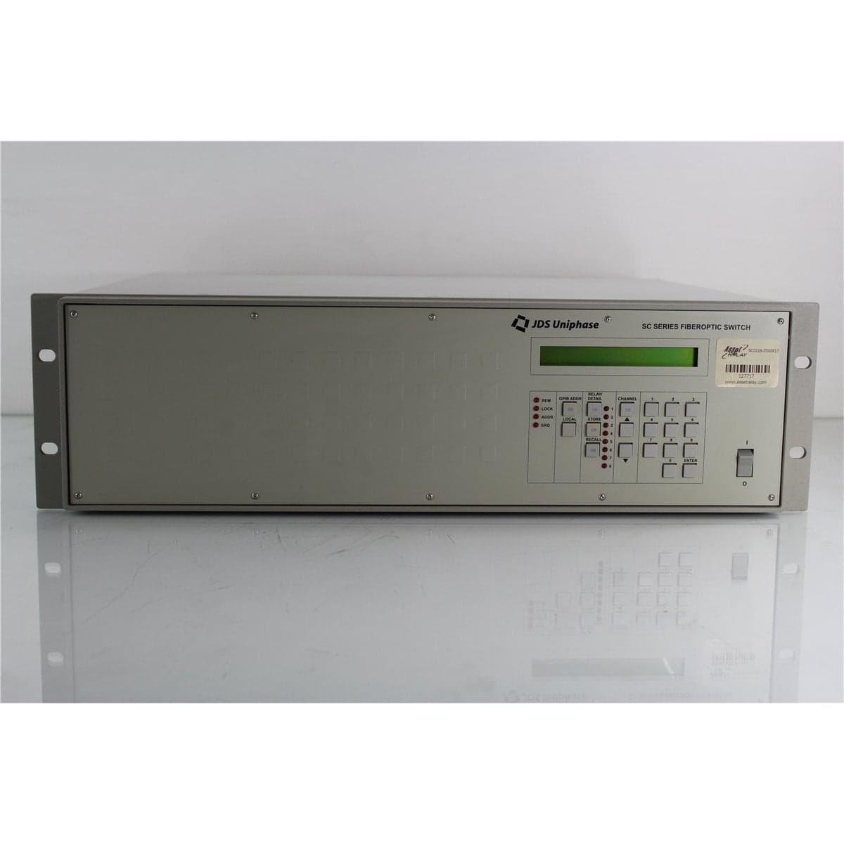
JDS FITEL SD Series Dual 1x16 Fiber Optic Switch with Pigtails
$3,192.00
Price in USD.
- Condition
- Used
- Availability
- In stock · 2 available
- Model
- SC0216-Z000817
- Manufacturer
- JDS
- Category
- Optical Switches 9-125 2xN
Description
JDS FITEL SD Series Dual 1x16 9/125 µm Single-Mode Optical Switch
The JDS FITEL SD Series Dual 1x16 Optical Switch is a programmable fiber optic routing instrument designed for laboratory, production, environmental testing, and automated optical measurement systems. It combines two independent 1x16 switch sections in a single enclosure, allowing two common optical paths to be routed separately across two banks of 16 selectable channels.
This unit is configured with 9/125 µm single-mode fiber and optical pigtails. The pigtail arrangement supports integration with connectorized test equipment, fiber optic assemblies, environmental chambers, production fixtures, and custom optical systems. Depending on the specific configuration, the pigtails may be connectorized or prepared for fusion splicing into a permanent installation.
The switch uses collimating lenses to align each common optical path with the selected output fiber. This optical design helps minimize loss and improve switching repeatability by maintaining controlled alignment between the internal channels. The selected paths are bidirectional, allowing compatible signals to travel through the switch in either direction.
Channel selection can be performed locally through the front-panel keyboard or remotely through the IEEE-488 interface. These control options make the switch useful for both manual optical routing and computer-controlled testing across multiple components, fibers, transmitters, receivers, sources, or detectors.
Features and Benefits of the JDS FITEL Dual 1x16 Optical Switch
- Dual independent 1x16 architecture: Provides two separate common optical ports, with each common port connected to its own bank of 16 selectable channels.
- 9/125 µm single-mode fiber: Supports compatible telecommunications, photonics, laboratory, and production test systems.
- Optical pigtail interfaces: Allows direct integration with connectorized equipment, custom fiber assemblies, or fusion-spliced optical systems.
- Bidirectional optical paths: Permits compatible signals to travel in either direction through the selected switch channel.
- Collimating-lens technology: Supports controlled optical alignment, low insertion loss, and repeatable channel selection.
- Programmable routing: Reduces manual reconnection of sources, detectors, devices under test, and measurement instruments.
- High switching repeatability: The documented switch platform provides repeatability better than 0.005 dB under stabilized launch conditions.
- Fast adjacent-port switching: Selects adjacent channels in less than 0.3 seconds.
- Front-panel control: Supports local channel selection for setup, troubleshooting, path identification, and manual testing.
- IEEE-488 automation: Enables computer-controlled channel selection and integration into automated optical test systems.
- Flexible wavelength configurations: The product family includes single-mode versions optimized for 1.3 µm or 1.55 µm operation.
- Multiple backreflection options: The family includes standard, low-backreflection, and ultra-low-backreflection optical configurations.
Dual 1x16 Switching Architecture
The SD Series architecture consists of two independent 1xN switch sections. In this configuration, each switch section contains one common optical port and 16 numbered channels. The first common port can be connected to one of the first 16 outputs, while the second common port can be connected independently to one of the second group of 16 outputs.
This arrangement provides two separately controlled optical routing functions. One switch section can distribute a source among several devices under test while the other section routes transmitted signals to a detector or measurement instrument. The two sections can also support separate test stations, comparative measurements, or independent optical systems.
The switch should not be described as a fully non-blocking 2x16 optical matrix. Each common port is associated with its own 16-channel bank and does not necessarily have unrestricted access to the channels assigned to the other switch section.
Automated Optical Signal Routing
The JDS FITEL Dual 1x16 Optical Switch can replace repeated manual changes to optical patch cords. A source, detector, receiver, power meter, backreflection meter, or other instrument can remain connected while the switch selects the required optical path.
Reducing manual connection changes can improve test throughput, protect optical connectors from unnecessary wear, and help maintain a controlled measurement setup. It can also reduce variations caused by repeated connector mating, fiber movement, and operator handling.
In an automated system, control software can select a channel through IEEE-488, allow the mechanism and optical path to settle, acquire a measurement from the connected instrument, and advance to the next channel. This process supports repeatable testing of multiple fibers, components, or devices.
Collimating-Lens Optical Design
The switching mechanism uses collimating lenses to connect a common optical path with a selected fixed fiber channel. The expanded optical beam is aligned internally before being coupled into the chosen output fiber.
This approach helps reduce modal-noise effects associated with direct gaps between fibers and contributes to repeatable optical coupling. The design supports repeated channel selection without requiring external optical connectors to be disconnected.
The switch is passive with respect to the transmitted optical signal. It does not generate, detect, amplify, attenuate intentionally, modulate, regenerate, or convert the wavelength of the signal. It establishes the selected optical path while introducing the applicable passive insertion loss.
9/125 µm Single-Mode Fiber
This switch is identified as a 9/125 µm single-mode configuration. It is intended for compatible single-mode optical sources, receivers, detectors, patch cords, passive components, transmitters, and fiber optic test instruments.
Compatible single-mode fiber should be used throughout the connected optical system. Substituting multimode fiber can alter coupling conditions and produce measurements that do not accurately represent the intended single-mode path.
The exact wavelength optimization should be confirmed from the complete instrument label or test data. The documented switch platform includes single-mode configurations optimized for operation around 1.3 µm and 1.55 µm.
Optical Pigtail Configuration
The switch uses optical pigtails rather than a complete group of removable panel-mounted bulkhead adapters. Depending on the individual configuration, the pigtails may exit from the front or rear panel and may be supplied with installed connectors or unterminated fiber ends.
Connectorized pigtails can be connected to matching patch cords, adapters, sources, or measurement instruments. Unterminated pigtails can be fusion spliced into a test fixture, optical rack, environmental chamber, production station, or permanent fiber assembly.
The documented product family specifies a standard pigtail length of 5 m. The actual length of the pigtails on this unit should be verified from the physical instrument because fibers may have been shortened, repaired, reterminated, or customized.
Bidirectional Optical Operation
The selected optical switch paths are bidirectional. A compatible optical signal can travel from the common port toward the selected numbered port or from a numbered port toward the common port.
Bidirectional operation supports source distribution, receiver selection, transmission testing, reflection measurements, remote monitoring, and setups in which the direction of signal travel changes during the test procedure.
The signal direction does not change the switch architecture. Each common port remains associated with its designated bank of 16 channels.
Insertion Loss
The applicable insertion loss depends on the wavelength optimization and backreflection configuration installed in the switch. The documented single-mode switch platform provides typical internal insertion loss as low as 0.4 dB for its standard backreflection configuration.
Single-mode low-backreflection configurations have typical internal insertion loss of 0.6 dB, while ultra-low-backreflection configurations have typical internal insertion loss of 0.9 dB. These values exclude losses introduced by external connectors.
The actual path loss can also include the optical pigtails, installed connectors, fusion splices, adapters, transition cables, and other components in the test setup. Each channel should be referenced or measured separately when precise insertion-loss values are required.
Backreflection Options
The JDS FITEL switch platform was available with standard, low-backreflection, and ultra-low-backreflection configurations. The selected option affects both the internal backreflection and insertion-loss performance.
| Configuration | Single-Mode Backreflection | Typical Internal Insertion Loss |
| Standard | Less than -25 dB | 0.4 dB |
| Low Backreflection | Less than -45 dB | 0.6 dB |
| Ultra-Low Backreflection | Less than -55 dB | 0.9 dB |
The exact backreflection option installed in this unit is not identified by the supplied product name. A standard, low, or ultra-low-backreflection rating should be assigned only after reviewing the complete model code or obtaining supporting optical test results.
Switching Repeatability
The documented switch platform provides switching repeatability better than 0.005 dB when launch conditions and source parameters are stabilized. Repeatable channel selection is useful when the same optical paths must be measured several times during qualification, production, or environmental testing.
Observed system repeatability also depends on the stability of the optical source, detector noise, connector cleanliness, pigtail movement, wavelength, polarization, fusion-splice quality, ambient conditions, and the device under test.
The switch, source, fibers, and receiving instrument should be allowed to stabilize before channel-to-channel comparisons or precision measurements are performed.
Switching Speed
Adjacent-port switching time is specified at less than 0.3 seconds. This supports sequential testing across multiple output channels without requiring manual movement of optical cables.
Total switching time may vary according to the distance between the current and requested positions. Automated software should allow enough time for the switch mechanism and connected measurement equipment to settle before accepting the reading.
Wavelength Configurations
The documented JDS FITEL switch family supports wavelength regions around 0.6 µm, 0.7 µm to 0.9 µm, and 1.2 µm to 1.6 µm, depending on the installed fiber and optical configuration.
For 9/125 µm single-mode versions, the ordering system includes configurations optimized around 1.3 µm and 1.55 µm. A special wavelength configuration was also available.
The complete model label should be reviewed to determine whether this switch is optimized for 1310 nm, 1550 nm, or another specified wavelength. Performance at both common single-mode wavelengths should not be assumed unless the individual unit has been verified accordingly.
Front-Panel and IEEE-488 Control
Local channel selection is available through the front-panel keyboard. This allows an operator to select switch sections and channels during setup, path identification, troubleshooting, and manual testing.
The IEEE-488 interface enables remote control from a compatible computer or instrument controller. Automated operation can coordinate the switch with optical sources, power meters, backreflection meters, attenuators, transmitters, receivers, and other test equipment.
IEEE-488 cables, interface cards, software, drivers, and control programs should be considered included only when specifically identified in the product listing.
Typical Applications
- Automated single-mode optical signal routing
- Fiber optic component transmission testing
- Optical reflection measurement systems
- Transmitter and receiver testing
- Optical light source selection
- Power meter and detector channel selection
- Fiber optic cable and assembly testing
- Environmental component testing
- Remote optical monitoring
- Production and quality-control testing
- Laboratory research and development
- Computer-controlled optical test systems
Product Overview
| Brand | JDS FITEL |
| Product Series | SD Series |
| Product Category | Programmable Single-Mode Fiber Optic Switch |
| Switch Architecture | Dual independent 1x16 |
| Common Optical Ports | Two, one per switch section |
| Selectable Channels | Two banks of 16 channels |
| Fiber Type | 9/125 µm single-mode fiber |
| Optical Connection Format | Pigtails |
| Optical Direction | Bidirectional |
| Local Control | Front-panel keyboard |
| Remote Interface | IEEE-488 |
| Primary Application | Programmable dual-bank optical routing for laboratory and production testing |
Supported Optical Specifications
| Specification | Details |
| Identified Fiber Type | 9/125 µm single-mode |
| Single-Mode Wavelength Options | 1.3 µm or 1.55 µm optimized configurations |
| Typical Internal Insertion Loss | As low as 0.4 dB, depending on configuration and excluding connectors |
| Switching Repeatability | Better than 0.005 dB under stabilized launch conditions |
| Adjacent-Port Switching Time | Less than 0.3 seconds |
| Optical Path Operation | Bidirectional |
| Documented Family Pigtail Length | 5 m |
| Connector Availability | Most common connector types were available within the product family |
Documented Connector Options
| Connector Code | Connector Type |
| NC | No connector |
| FC | FC |
| FP | FC/PC |
| ST | ST |
| SP | ST/PC |
| D4 | D4 |
| DP | D4/PC |
| BC | Biconic |
| SA | Biconic SPA |
| SC | SC/PC |
| FA | FC/APC |
Documented Pigtail and Port Arrangements
| Port Code | Port Arrangement |
| 0 | Pigtails on rear panel, single-height enclosure |
| 1 | Pigtails on front panel, single-height enclosure |
| 2 | Bulkheads on front panel, single-height enclosure |
| 3 | Pigtails on rear panel, double-height enclosure |
| 4 | Pigtails on front panel, double-height enclosure |
| 5 | Bulkheads on front panel, double-height enclosure |
Electrical and Control Specifications
| Specification | Details |
| Local Control | Front-panel keyboard |
| Remote Control | IEEE-488 interface |
| Operating Voltage | 110 V to 240 V AC |
| Line Frequency | 50 Hz to 60 Hz |
| Power Consumption | 30 W |
Environmental Specifications
| Specification | Details |
| Operating Temperature | 0 °C to 40 °C |
| Storage Temperature | -40 °C to 60 °C |
Physical Specifications
| Configuration | Dimensions or Weight |
| Single-Height Benchtop Enclosure | 44 cm wide x 16 cm high x 38 cm deep |
| Single-Height Rack-Mount Enclosure | 48 cm wide x 16 cm high x 43 cm deep |
| Single-Height Unpackaged Weight | Approximately 9 kg |
| Single-Height Shipping Weight | Approximately 15 kg |
Optical Path Identification
The common port and output pigtails for each 1x16 switch section should be positively identified before installation. Channel labels should be recorded so the correct switch bank and output position are selected during manual or automated operation.
A stable optical source and compatible power meter can be used to map the switch. The source is connected to the common port of one section, and each possible output is monitored while the channel position is changed. The process is then repeated for the second switch section.
Control software should use the verified optical map rather than relying exclusively on fiber color, bundle position, or assumptions based on the enclosure layout.
Pigtail and Connector Care
All pigtails should be routed with an appropriate bend radius and protected from tension, twisting, crushing, abrasion, and sharp equipment edges. Mechanical stress near the enclosure exit can increase optical loss or damage the fiber.
If connectors are installed, every connector end face should be inspected and cleaned before mating. The connector type and polish must match the connected equipment. APC and non-angled physical-contact connectors should not be directly intermated.
Protective caps should remain installed whenever connectorized pigtails are not in use. Dust caps should also remain clean so they do not transfer contamination back to the optical interfaces.
If the pigtails are unterminated, fusion splicing should use a process appropriate for the installed 9/125 µm single-mode fiber. Completed splices should be protected and tested at the operating wavelength required by the application.
Comprehensive Functional and Performance Testing
The JDS FITEL SD Series Dual 1x16 Optical Switch receives comprehensive functional and performance testing before shipment. Evaluation may include AC power operation, startup, display condition, front-panel keyboard response, channel selection, switch-bank selection, IEEE-488 communication, and independent operation of both 1x16 switch sections.
Optical testing may include common-port identification, output-channel mapping, continuity through representative paths, insertion-loss comparison, adjacent-port switching time, repeated channel selection, and bidirectional optical transmission.
The pigtails, installed connectors, fiber coatings, strain relief, enclosure exits, channel labels, front-panel controls, IEEE-488 interface, AC inlet, enclosure, handles, and cooling openings may be inspected for damage, contamination, wear, or mechanical problems.
The exact testing scope depends on the wavelength optimization, backreflection configuration, port arrangement, connector type, quantity of accessible channels, available optical sources, calibrated power meters, and supporting test equipment.
Buyer Considerations
The supplied description identifies a JDS 9/125 µm optical switch with dual 1x16 architecture and optical pigtails. The complete model and option code should be reviewed before assigning a specific wavelength, backreflection rating, connector type, pigtail location, pigtail length, or enclosure configuration.
Buyers should confirm that the required application is compatible with two independent 1x16 switches. This configuration is not necessarily equivalent to a fully non-blocking 2x16 matrix switch.
The listing should identify whether the pigtails are bare or connectorized and, when connectorized, the installed connector type and polish. The condition and labeling of all common and numbered paths should also be reviewed.
Only the optical switch, attached pigtails, installed connectors, protective caps, power cord, IEEE-488 cable, rack hardware, software, manuals, calibration records, and accessories specifically identified in the product listing should be considered included.
Why Buy from AssetRelay?
AssetRelay supplies professional equipment and product solutions for fiber optic, telecom, laboratory, production, optical testing, photonics, inspection, cleaning, electronic testing, RF/microwave, and technical research applications. This JDS FITEL Dual 1x16 Optical Switch supports component manufacturers, telecommunications laboratories, production facilities, system integrators, service organizations, universities, and research teams requiring repeatable multi-channel optical routing.
Buyers should review the complete model label, 9/125 µm fiber configuration, wavelength optimization, backreflection option, pigtail location and condition, connector type, both 1x16 switch sections, channel mapping, IEEE-488 operation, functional test results, and included accessories before purchase.