
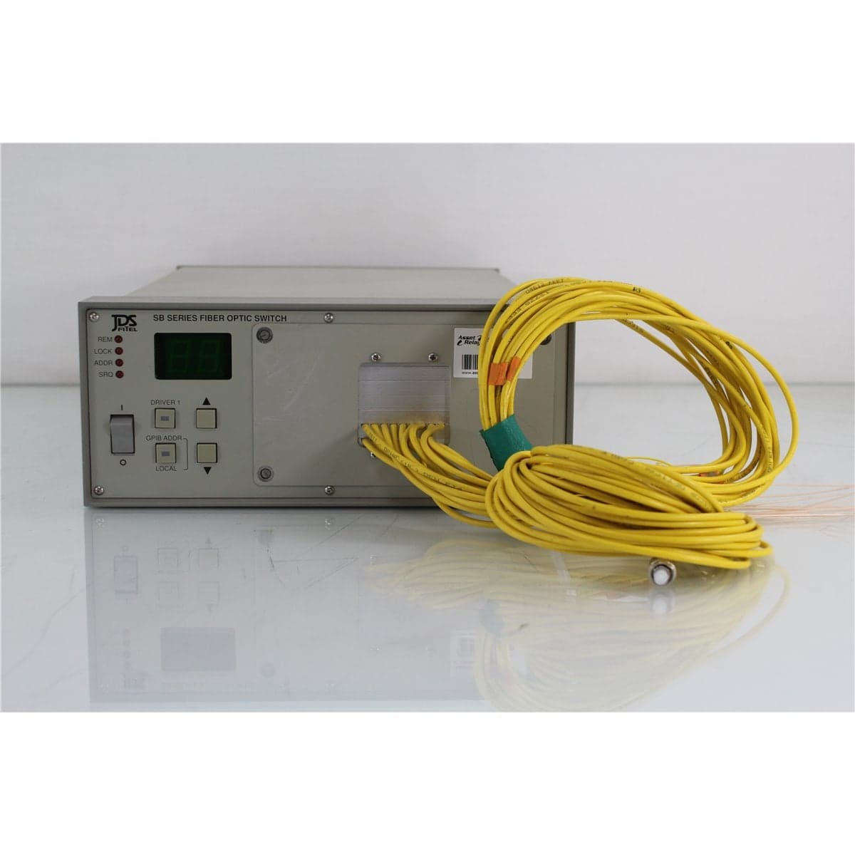
JDS · SB16B5-CINC
JDS Uniphase SB16B5-CINC 1x16 Single-Mode Programmable Optical Switch
$2,712.00
Price in USD.
- Condition
- Used
- Availability
- In stock
- Model
- SB16B5-CINC
- Manufacturer
- JDS
- Category
- Optical Switches 9-125 1xN
Description
JDSU MAP Dual-Channel 50/125 µm Multimode Variable Optical Attenuator with Power Meter
The JDSU MAP Dual-Channel Multimode Variable Optical Attenuator is a modular optical test solution that combines two independently controlled attenuation channels with integrated optical power monitoring. It is designed for use with 50/125 µm multimode fiber in compatible JDSU Multiple Application Platform test systems.
Each channel provides controlled optical attenuation and power measurement within a compact modular platform. This dual-channel configuration is useful for testing duplex optical transceivers, parallel receiver paths, multimode components, optical links, and other devices that require two independently managed optical signals.
The integrated optical power monitors allow each channel’s output level to be observed without requiring a separate external power meter and optical tap for every measurement. Depending on the installed module configuration and host-system software, this measurement feedback can support closed-loop optical power control for repeatable automated testing.
The complete module part number should be confirmed from the physical product label. The general description identifies a dual-channel 50/125 µm multimode attenuator with power monitoring, but it does not establish the exact attenuation range, connector family, connector polish, standard-power or high-power configuration, wavelength calibration, or installed options.
Features and Benefits of the JDSU Dual-Channel Multimode Attenuator
- Dual independent channels: Provides separate attenuation control for two multimode optical paths.
- Integrated optical power monitoring: Measures the optical output level of each channel within the module.
- 50/125 µm multimode fiber: Supports compatible multimode sources, transceivers, receivers, patch cords, and optical components.
- Programmable attenuation: Allows optical signal levels to be adjusted through a compatible JDSU MAP chassis.
- Closed-loop testing capability: Integrated power measurement can support automatic adjustment to a programmed output level when the applicable module and software functions are available.
- Receiver sensitivity testing: Reduces optical power in controlled steps for evaluating compatible optical receivers.
- Optical loss simulation: Reproduces different link-loss conditions without repeatedly changing fixed attenuators.
- Duplex transceiver testing: Supports independent control of two optical paths in compatible dual-channel systems.
- Automated test integration: Operates within a compatible MAP platform for computer-controlled laboratory and production measurements.
- Reduced test-system complexity: Combines attenuation and power monitoring in one modular optical instrument.
- Reusable modular design: Can be integrated with compatible JDSU optical sources, switches, meters, and related MAP modules.
Dual-Channel Optical Attenuation
The module contains two independently controlled variable optical attenuator channels. Each channel can be connected to a separate optical source, device under test, receiver path, or reference path.
Independent operation allows different attenuation values to be applied to each optical channel. This is useful when evaluating duplex transceivers, paired receivers, dual-wavelength arrangements, or devices with separate optical inputs.
The channels can also be used as measurement and reference paths. One channel can establish a known optical condition while the other channel is adjusted during component or receiver testing.
50/125 µm Multimode Fiber Configuration
This module is configured for 50/125 µm multimode fiber. Compatible 50/125 µm patch cords, optical sources, detectors, receivers, and devices under test should be used throughout the optical path.
Multimode measurements can be affected by source launch conditions, modal distribution, numerical aperture, connector alignment, patch-cord routing, fiber bends, and detector geometry. Reference cables and launch conditions should remain consistent during comparative or calibrated testing.
Single-mode and 62.5/125 µm multimode patch cords should not be substituted when the measurement procedure requires controlled 50/125 µm operation.
Integrated Optical Power Measurement
Each attenuator channel includes an integrated optical power-monitoring function. This allows the module to observe the signal level after attenuation and provide the measured result to the compatible MAP host system.
Integrated monitoring reduces the need for a separate external power meter in applications where the attenuated output level must be supervised continuously. It can also simplify optical test fixtures by reducing the number of external connections and instruments.
The host system can display and record optical measurements according to the module configuration and software capabilities. The correct measurement wavelength should be selected because detector response varies across the optical spectrum.
Closed-Loop Optical Power Control
When supported by the complete module configuration, integrated power monitoring can be used for closed-loop output control. The module measures its output and adjusts attenuation until the programmed power level is achieved.
This function helps compensate for supported changes in source output and upstream optical loss. It is useful in automated receiver sensitivity measurements and production tests requiring repeatable power at the device under test.
Closed-loop operating range, accuracy, repeatability, and wavelength calibration depend on the complete module option code and should be verified before specific numerical values are assigned.
Optical Receiver Sensitivity Testing
A variable optical attenuator is commonly used to determine the minimum optical power at which a receiver continues to meet its required performance level. The optical level is reduced while the receiver response, error rate, alarm state, or other performance indicator is monitored.
The dual-channel module can support two receiver paths or separate test and reference channels. Automated attenuation steps can be coordinated with compatible bit-error-rate test equipment, transceiver interfaces, and data-acquisition software.
The connected receiver’s maximum and minimum optical input ratings should be reviewed before testing begins. Initial setup should use a high attenuation value to protect sensitive receiver inputs.
Multimode Transceiver Testing
The module is suitable for compatible multimode transceiver and optical module testing. Applications can include transmitter-output control, receiver sensitivity evaluation, overload testing, optical loss simulation, and repeated production measurements.
Dual attenuation channels can support duplex or two-lane optical arrangements. The exact test configuration depends on transceiver type, wavelength, connector interface, data rate, launch condition, and required measurement method.
The attenuator does not generate a data signal or perform bit-error-rate measurements independently. Appropriate optical sources, transceiver fixtures, signal generators, receivers, and measurement instruments are required for a complete test system.
Optical Shutter Operation
Compatible JDSU MAP attenuator modules include optical shutter functions for interrupting the optical signal without changing the programmed attenuation setting. This supports dark measurements, receiver protection, and automated signal-on and signal-off test sequences.
The exact shutter isolation and response time should be confirmed from the complete module model and installed configuration.
The shutter should not replace standard optical safety procedures. Optical sources should still be disabled before connectors are inspected, cleaned, installed, or removed.
MAP Platform Integration
The dual-channel attenuator is designed for installation in a compatible JDSU Multiple Application Platform chassis. The host platform supplies electrical power and provides module recognition, local control, software functions, data management, and remote communication.
The modular architecture allows the attenuator to operate alongside compatible optical switches, sources, power meters, and other photonic test modules. This supports compact and configurable laboratory or production systems.
The module cannot operate as a standalone benchtop attenuator. Chassis generation, controller compatibility, firmware revision, available slot capacity, and software support should be verified before installation.
Typical Applications
- 50/125 µm multimode receiver sensitivity testing
- Dual-channel transceiver evaluation
- Optical signal-level control
- Multimode link-loss simulation
- Integrated optical power monitoring
- Duplex optical path testing
- Optical detector characterization
- Multimode component testing
- Automated optical-level sweeps
- Manufacturing and production testing
- Laboratory test-system integration
- Telecommunications research and development
Product Overview
| Brand | JDSU |
| Product Family | MAP Series |
| Product Category | Dual-Channel Variable Optical Attenuator with Power Monitoring |
| Number of Channels | Two independently controlled optical channels |
| Fiber Type | 50/125 µm multimode fiber |
| Integrated Measurement | Optical power monitoring |
| Control Platform | Compatible JDSU Multiple Application Platform chassis |
| Standalone Operation | Not supported |
| Primary Application | Dual-channel multimode optical attenuation and output-power monitoring |
Confirmed Configuration
| Configuration Item | Details |
| Attenuator Channels | Two |
| Fiber Core and Cladding | 50/125 µm multimode |
| Power Measurement | Integrated optical power-monitoring function |
| Installation Format | Plug-in MAP optical test module |
| Operating Environment | Compatible modular laboratory and production test platform |
Configuration Details Requiring Verification
| Configuration Item | Verification Required |
| Complete Model Number | Confirm the complete JDSU module code from the physical label |
| Module Generation | Confirm the exact MAP attenuator family and compatible chassis generation |
| Attenuation Range | Confirm from the complete model and factory configuration |
| Wavelength Range | Confirm the supported multimode wavelength range and calibration wavelengths |
| Optical Connector Type | Confirm FC, SC, LC, or another connector family and ferrule polish |
| Input-Power Rating | Confirm standard-power or high-power configuration |
| Closed-Loop Power Range | Confirm the supported programmed output-power range |
| Slot Requirement | Confirm the number of chassis positions occupied by the module |
Installation and System Integration
The module should be installed in a compatible JDSU MAP chassis according to the applicable installation procedure. The module should be seated securely and recognized by the host platform before optical connections are made.
Compatible 50/125 µm multimode patch cords should be connected to the two attenuation channels. Connector type and ferrule polish must match the optical interfaces installed on the module.
When a sensitive receiver or detector is connected, each channel should initially be set to a high attenuation value or low programmed output level. Optical power can then be increased gradually while the receiving equipment is monitored.
The source wavelength should match the power-monitor calibration setting. The module and host chassis should complete the applicable warm-up period before precision measurements are recorded.
Connector Inspection and Cleaning
Every optical port and mating patch cord should be inspected before connection. Contaminated fiber end faces should be cleaned using an approved fiber optic process and reinspected before mating.
Clean optical interfaces help maintain insertion loss, attenuation accuracy, power-meter response, repeatability, and connector condition. Connector cleanliness is especially important when higher optical input levels are used.
Protective caps should remain installed on unused optical ports. Only clean caps should be placed on cleaned interfaces.
Comprehensive Functional and Performance Testing
The JDSU dual-channel multimode attenuator receives comprehensive functional and performance testing before shipment. Evaluation may include installation in a compatible MAP chassis, module recognition, startup, independent control of both channels, attenuation adjustment, power-monitor response, closed-loop operation when supported, and shutter control.
Optical testing may include input-to-output continuity, insertion loss, representative attenuation points, repeatability, power-monitor response, and output-power control for both channels using compatible 50/125 µm multimode equipment.
The optical interfaces, module faceplate, chassis connector, enclosure, labels, and installed option markings may be inspected for contamination, damage, corrosion, deformation, fiber stress, or excessive wear.
The exact testing scope depends on the complete model number, optical connector type, power version, compatible chassis, available multimode sources, reference cables, calibrated power meters, and requested wavelengths and power levels.
Calibration Before Shipment
When technically applicable and selected, the JDSU dual-channel multimode attenuator can be calibrated or performance-verified before shipment. Evaluation may include insertion loss, attenuation accuracy, attenuation repeatability, power-monitor accuracy, closed-loop output settings, wavelength response, and shutter isolation for both channels.
Calibration documentation should identify the module model and serial number, channel, fiber type, optical connector, host chassis, test wavelength, input power, attenuation setting, output power, reference patch cords, measurement equipment, recorded results, and applicable measurement uncertainty.
Buyers requiring formal calibration should specify the complete model number, required channels, wavelengths, attenuation points, optical power levels, connector configuration, certificate format, recorded data, and required uncertainty before purchase.
Buyer Considerations
Buyers should obtain the complete module part number before finalizing compatibility or numerical specifications. The general description confirms two attenuation channels, 50/125 µm multimode fiber, and integrated power monitoring but does not identify every installed option.
The product listing should identify the connector type, standard-power or high-power configuration, compatible MAP chassis, occupied slot count, included protective caps, optical patch cords, software, manuals, test report, and calibration documentation.
Only the JDSU attenuator module and accessories specifically identified in the product listing should be considered included.
Why Buy from AssetRelay?
AssetRelay supplies professional equipment and product solutions for fiber optic, telecommunications, optical testing, photonics, laboratory, production, inspection, electronic testing, RF/microwave, and technical research applications. This JDSU dual-channel multimode attenuator supports transceiver manufacturers, receiver developers, optical component producers, telecommunications laboratories, production facilities, system integrators, universities, and research organizations.
Buyers should review the complete model number, dual-channel operation, 50/125 µm fiber configuration, integrated power monitors, connector type, attenuation and power ranges, chassis compatibility, functional test results, calibration status, and included accessories before purchase.