
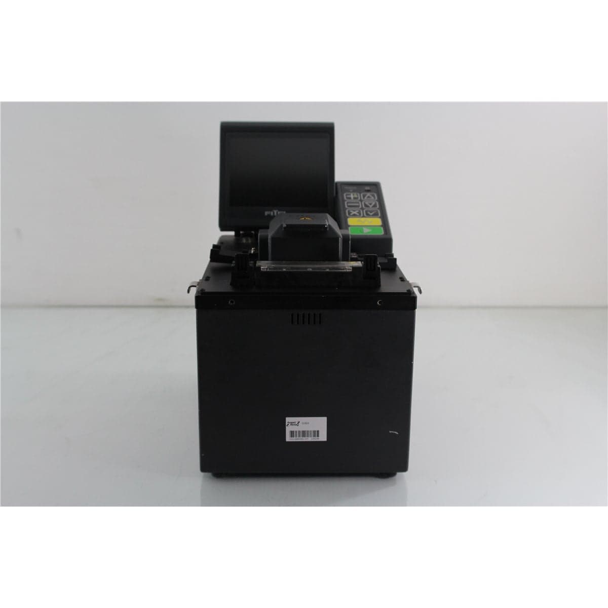
Fitel · S182K
FITEL S182K High-Strength Specialty Fiber Fusion Splicer
$2,400.00
Price in USD.
- Condition
- Used
- Availability
- In stock · 3 available
- Model
- S182K
- Manufacturer
- Fitel
- Category
- Fusion Splicers
Description
FITEL S182K High-Strength Core-Alignment Fusion Splicer for Dissimilar Specialty Fibers
The FITEL S182K is a high-strength specialty fiber fusion splicer designed for joining dissimilar fiber pairs in demanding photonics, laboratory, research, and production environments. It uses a Profile Alignment System with core alignment to position fibers before fusion, helping operators control core offset and produce consistent splices between compatible fibers with different optical or physical properties.
The S182K supports compatible single-mode, multimode, dispersion-shifted, and erbium-doped fibers in dissimilar pairings. These capabilities make the splicer suitable for specialty fiber processing in fiber laser manufacturing, optical amplifier development, optical sensor assembly, telecommunications research, component production, and other applications where conventional telecom fusion splicers may not provide the required process flexibility.
High-strength fiber processing requires careful control of stripping, cleaning, cleaving, handling, alignment, and fusion. When the S182K is used with the appropriate FITEL high-strength accessories, its fiber-handling arrangement prevents the prepared bare glass from contacting the V-grooves. This helps protect the stripped fiber surface from scratches and mechanical damage that could reduce the strength of the completed splice.
Features and Benefits of the FITEL S182K
- Designed for dissimilar specialty fibers: Supports compatible single-mode, multimode, dispersion-shifted, and erbium-doped fiber pairs with differing optical or physical characteristics.
- Profile Alignment System: Uses profile imaging and core alignment to position the fibers before fusion.
- High-strength fiber handling: The appropriate accessory configuration prevents bare prepared fiber from contacting the V-grooves.
- High tensile-strength capability: FITEL documents an average splice tensile strength of 300 kpsi under its laboratory conditions.
- Simultaneous X and Y views: Displays the fibers from two directions for alignment and visual inspection.
- Five-inch color monitor: Provides 264x magnification for viewing alignment and splice conditions.
- Typical 20-second splice time: Provides a typical fusion cycle of 20 seconds for compatible single-mode fiber.
- Flexible splice programming: Includes 26 preprogrammed splice programs and six customizable program locations.
- Detailed inspection functions: Evaluates cleave angle, end gap, core eccentricity, offset, tilt, microbending, bubbling, thickening, and streaking.
- Integrated tension test: Provides a documented 200 g tension-test function.
- Protection sleeve heater: Includes four preset and four customizable heater programs.
- Splice data storage: Stores information for as many as 400 splices.
- Environmental sensing: Monitors air pressure, temperature, and humidity.
- Remote-control capability: Supports optional hands-free operation from a compatible computer through RS-232C.
Specialty Fiber and Dissimilar Fiber Splicing
The S182K is intended for applications in which the two fibers being joined may not have identical optical or mechanical characteristics. The supported fiber categories include single-mode, multimode, dispersion-shifted, and erbium-doped fibers.
Dissimilar fiber pairs can vary in core diameter, mode-field diameter, dopant concentration, cladding geometry, glass composition, thermal response, and coating construction. These differences can affect alignment, arc behaviour, splice appearance, optical loss, and mechanical strength.
The correct fusion program should be selected according to the properties of both fibers. The S182K provides preprogrammed settings for supported applications and customizable program locations for qualified users developing processes for specialized fiber combinations.
The finished splice should be validated according to the application. Optical loss testing, visual examination, proof testing, tensile testing, or fiber recoating may be required before the splice is accepted for use in a component or optical system.
Profile Alignment System with Core Alignment
The FITEL S182K uses a Profile Alignment System to observe the fibers and align their cores before fusion. The system displays simultaneous X-axis and Y-axis views, allowing the fibers to be examined from two directions.
Core alignment is useful when the core is not perfectly concentric with the cladding or when the fibers have different geometric characteristics. Aligning according to the observed core position can help reduce lateral offset and improve coupling between the joined fibers.
The splicer uses a five-inch color display with 264x magnification. The main screen can show operating messages, the arc counter, time, heater status, estimated splice loss, and the simultaneous X and Y images.
The alignment system should be kept clean and properly maintained. Contamination on the V-grooves, fiber clamps, mirrors, cameras, or prepared fiber can interfere with image quality and positioning accuracy.
High-Strength Splicing Process
The high-strength capability of the S182K depends on the complete fiber preparation and handling process. With the correct high-strength accessories, the bare fiber is supported without contacting the V-grooves, reducing the potential for surface damage before fusion.
FITEL reports an average tensile strength of 300 kpsi under laboratory conditions. This value reflects a controlled process using appropriate fibers, preparation equipment, holders, cleaning methods, fusion parameters, and mechanical testing procedures.
Actual splice strength can vary according to fiber composition, coating-removal method, stripped length, cleave quality, handling, cleanliness, environmental conditions, electrode condition, arc parameters, and proof-test method. The documented result should not be interpreted as a guaranteed strength for every fiber combination or production process.
Applications requiring certified mechanical performance should establish a validated preparation, splicing, recoating, curing, and tensile-testing procedure for the exact fibers being used.
Fiber Preparation and Cleave Requirements
For high-strength applications involving fibers with 250 µm or 400 µm coatings, the documented cleave length is 3 mm to 5 mm. The appropriate high-strength fiber holders, stripping equipment, cleaver, and cleaning system are required.
The S182K can also support compatible 900 µm coated fiber using a 16 mm or 11 mm cleave length. These 900 µm configurations use the appropriate normal-strength V-grooves, fiber holders, and thermal stripping equipment and are not identified as high-strength configurations.
The selected coating diameter and cleave length must match the installed V-grooves and fiber holders. An incorrect combination can interfere with fiber loading, end-gap control, core alignment, electrode positioning, or splice-chamber clearance.
Prepared fiber ends should be clean and free from coating residue, dirt, dust, cleaning fluid, chips, or cleave defects. Fibers should be loaded without contacting the stripped glass unnecessarily.
Splice Programs and Process Development
The FITEL S182K includes 26 preprogrammed splice programs and six customizable program locations. The factory programs provide starting points for supported fiber categories, while the customizable positions allow specialized processes to be developed and stored.
Custom settings can be useful for fibers with unusual dopant profiles, different mode-field diameters, specialty claddings, uncommon coatings, or significantly different melting behaviour. Process development should be completed carefully by personnel familiar with specialty fiber fusion.
A custom program should be validated using representative fibers and the required performance criteria. Appropriate validation can include measured splice loss, visual geometry, proof testing, tensile strength, return loss, mode-field behaviour, and long-term environmental performance.
Custom programs available for one fiber pair should not be assumed to be suitable for a different fiber combination without additional testing.
Estimated Splice Loss
The S182K provides estimated splice-loss information as part of its displayed results. Published average loss values are 0.03 dB for compatible single-mode fiber, 0.02 dB for compatible multimode fiber, and 0.05 dB for compatible dispersion-shifted fiber.
Estimated loss is calculated from the fiber images and observed splice conditions. It provides useful process feedback but is not a substitute for a direct optical loss measurement when documented insertion loss is required.
Actual measured loss can be influenced by core alignment, mode-field mismatch, core diameter, fiber numerical aperture, splice geometry, dopant diffusion, launch conditions, test wavelength, and the optical measurement method.
Dissimilar specialty fiber pairs may produce results that differ from the published averages. The exact fiber combination should be tested using appropriate stabilized optical sources and calibrated detectors.
Fiber and Splice Inspection Functions
The S182K includes inspection functions for evaluating fiber preparation, alignment, and visible splice conditions. These functions help identify problems before the fiber proceeds to recoating, protection, or final product assembly.
- Cleave angle: Evaluates the angle of the prepared fiber end and helps identify inadequate cleaves.
- Fiber end gap: Checks the separation between the two fiber ends before fusion.
- Core eccentricity: Evaluates the relationship between the observed core and cladding.
- Fiber offset: Detects lateral displacement between the fibers.
- Fiber tilt: Identifies angular misalignment before fusion.
- Microbending: Helps identify localized deformation that may affect alignment or splice quality.
- Bubbling: Detects visible bubbles or void-like defects in the fused region.
- Thickening: Identifies excessive enlargement of the fiber at the splice.
- Streaking: Detects visible streaks or irregular fusion patterns.
Inspection results should be considered together with the fiber type, selected program, alignment images, estimated loss, and any required optical or mechanical verification.
Integrated Tension Test
The FITEL S182K includes a documented 200 g tension-test function. This test applies a controlled proof load to the completed fiber splice.
A tension test can help identify weak splices caused by poor cleaves, inadequate fusion, contaminated fibers, surface damage, or other process problems. The built-in test is useful for routine splice verification but does not replace higher-force tensile testing when an application requires documented high-strength performance.
Verification of a 300 kpsi process requires suitable fiber geometry information, calibrated mechanical test equipment, a validated test method, and acceptance criteria appropriate for the fiber and application.
Protection Sleeve Heater
The integrated heater provides a typical protection cycle of 90 seconds. Four preprogrammed heater programs support compatible 20 mm, 25 mm, 40 mm, and 60 mm protection sleeves.
Four customizable heater-program locations allow qualified users to adjust the heating process for compatible sleeves or assemblies requiring different time and temperature characteristics.
The protection method should be selected according to the fiber diameter, coating, mechanical requirements, available space, and intended use. Specialty applications may require recoating rather than a conventional heat-shrink protection sleeve.
Splice Memory and Production Records
The S182K stores information for as many as 400 splices. Splice memory can support process review, production tracking, equipment monitoring, and troubleshooting.
The arc counter provides additional maintenance information and can help users monitor electrode usage. Electrode condition directly affects arc stability and should be evaluated as part of routine splicer maintenance.
Stored information should be supplemented with external records when an application requires traceability for fiber lot, operator, splice program, date, optical loss, tensile strength, or recoating results.
Environmental Sensors and Arc Control
The S182K includes sensors for air pressure, temperature, and humidity. Environmental conditions can influence arc discharge and fusion behaviour, particularly in applications involving specialty glass compositions or demanding mechanical requirements.
Environmental sensing supports more consistent operation across changing laboratory or production conditions. The splicer should still be used in a clean, stable environment whenever possible.
Airflow, rapid temperature changes, dust, vibration, and high humidity can affect fiber handling, image quality, cleave condition, and arc performance. The work area should be maintained according to the requirements of the fiber process.
Remote-Control Capability
An optional remote-control program is available for the S182 Series. The software supports hands-free splicer operation from a compatible computer, which can be useful in automated fixtures, production workstations, research setups, and enclosed fiber-processing systems.
The S182K provides an RS-232C data interface through a 9-pin male D-sub connector. A PIN-plug video connection is also provided.
Remote-control software, interface cables, licensing, computer hardware, and operating-system compatibility should be confirmed before the splicer is integrated into an automated system.
Typical Applications
- Dissimilar specialty fiber splicing
- Erbium-doped fiber assembly
- Fiber laser manufacturing and research
- Optical amplifier development
- Photonics component production
- Optical sensor assembly
- Dispersion-shifted fiber splicing
- Specialty single-mode fiber joining
- Specialty multimode fiber joining
- High-strength fiber assembly
- Laboratory fiber process development
- Automated specialty fiber production
Product Overview
| Brand | FITEL |
| Model | S182K |
| Product Category | High-Strength Specialty Fiber Fusion Splicer |
| Alignment Method | Profile Alignment System with core alignment |
| Applicable Fiber Categories | Single-mode, multimode, dispersion-shifted, and erbium-doped dissimilar fiber pairs |
| Typical Single-Mode Splice Time | 20 seconds |
| Splice Program Capacity | 26 preprogrammed and six customizable programs |
| Splice Memory | 400 records |
| Primary Application | High-strength fusion splicing of dissimilar specialty fibers |
Splicing Specifications
| Specification | Details |
| Splicing Method | Profile Alignment System with core alignment |
| S182K Fiber Pairing | Dissimilar SM, MM, DS, and EDF fiber pairs |
| Average Single-Mode Splice Loss | 0.03 dB |
| Average Multimode Splice Loss | 0.02 dB |
| Average Dispersion-Shifted Fiber Splice Loss | 0.05 dB |
| Typical Single-Mode Splice Time | 20 seconds; time varies according to fiber type |
| Preprogrammed Splice Programs | 26 |
| Customizable Splice Programs | Six |
| Documented Average Tensile Strength | 300 kpsi under FITEL laboratory conditions |
| Built-In Tension Test | 200 g |
| Splice Memory | 400 records |
Fiber Preparation Specifications
| Coating Configuration | Cleave Length | Application |
| 250 µm or 400 µm | 3 mm to 5 mm | High-strength splicing with appropriate accessories |
| 900 µm | 16 mm | Normal-strength configuration with corresponding V-grooves, holders, and stripper |
| 900 µm, 400 µm, or 250 µm | 11 mm | Normal-strength configuration with corresponding V-grooves, holders, and stripper |
Protection Heater Specifications
| Specification | Details |
| Typical Protection Cycle | 90 seconds |
| Preprogrammed Heater Programs | Four |
| Supported Preset Sleeve Lengths | 20 mm, 25 mm, 40 mm, and 60 mm |
| Customizable Heater Programs | Four |
Display, Inspection, and Sensor Specifications
| Specification | Details |
| Monitor | 5-inch color display |
| Magnification | 264x |
| Fiber Views | Simultaneous X-axis and Y-axis views |
| Main Display Information | Operating messages, arc counter, time, heater status, estimated loss, and X and Y views |
| Fiber Inspection | Cleave angle, end gap, core eccentricity, offset, tilt, and microbending |
| Splice Inspection | Bubbling, thickening, streaking, and other detected splice errors |
| Environmental Sensors | Air pressure, temperature, and humidity |
| V-Groove Illumination | LED |
Interface and Power Specifications
| Specification | Details |
| Data Interface | RS-232C through a 9-pin male D-sub connector |
| Video Interface | PIN plug |
| Remote Control | Optional compatible S182 Series remote-control program |
| AC Power | 100 V to 120 V AC or 200 V to 240 V AC |
Physical and Environmental Specifications
| Specification | Details |
| Width | 180 mm |
| Depth | 260 mm |
| Height | 160 mm |
| Weight | Approximately 7.5 kg |
| Operating Temperature | -10 °C to 50 °C |
| Storage Temperature | -40 °C to 60 °C |
Standard S182K Package Components
| Component | Model or Description |
| Main Body | S182K-01 |
| Top Cover | S182X-02 |
| AC Power Cord | S182X-03 |
| Spare S182K Electrodes | S182K-04, one pair |
| Spare Fuse | S182X-05 |
| Left V-Groove for 250/400 µm Fiber | S182X-06 |
| Right V-Groove for 250 µm Fiber | S182X-07 |
| Right V-Groove for 400 µm Fiber | S182X-08 |
| Operation Manual | Standard documentation |
Compatible Optional Accessories
| Accessory | Model | Application |
| High-Strength Cleaver | S323F | High-strength fiber cleaving with the appropriate holder attachment |
| Ultrasonic High-Precision Cleaver | S391 | Precision cleaving for S182A and S182K applications |
| High-Strength Hot Stripper | S218F | High-strength coating removal with the appropriate holder attachment |
| Automated Thermal Stripper | S291 | Automatic stripping with an adjustable strip length |
| High-Strength Fiber Holders | S705S-025 | Pair of holders for compatible 250 µm or 400 µm fibers |
| Ultrasonic Cleaning Kit | S182X-20 | Cleaner, beaker, and fiber-holder adapter |
| 900 µm Fiber Holders | S705S-090 | Pair of holders for compatible 900 µm fibers |
| Fiber Recoater | S541A | Automatic resin injection, curing, and tensile testing |
| 20 mm Mini Protection Sleeves | S925F-20mm | Single-fiber protection sleeves |
| 25 mm Mini Protection Sleeves | S926F-25mm | Single-fiber protection sleeves |
| 40 mm Protection Sleeves | S922F-40mm | Single-fiber protection sleeves |
| 60 mm Protection Sleeves | S921F-60mm | Single-fiber protection sleeves |
| Remote-Control Program | RCP | Computer control of compatible S182 Series fusion splicers |
Comprehensive Functional and Performance Testing
The FITEL S182K receives comprehensive functional and performance testing before shipment. Evaluation may include AC power operation, startup, display condition, keypad response, simultaneous X and Y fiber imaging, camera focus, V-groove illumination, environmental sensor operation, heater response, arc generation, program access, splice-memory functions, arc-counter operation, tension-test function, and RS-232C communication.
The electrode area, V-grooves, fiber clamps, cameras, mirrors, heater, fiber-loading area, and installed holders may be inspected for contamination, wear, damage, or alignment problems. Electrode condition and arc stability may also be reviewed.