
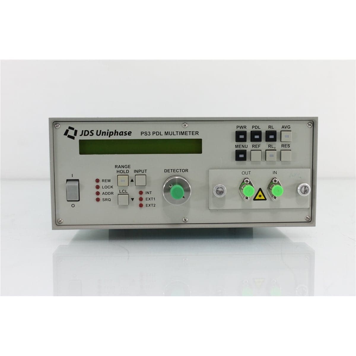
JDS · PS3650
JDS Uniphase PS3650 PS3 1550 nm Polarization-Dependent Loss Multimeter
$3,560.00
Price in USD.
- Condition
- Used
- Availability
- In stock · 4 available
- Model
- PS3650
- Manufacturer
- JDS
- Category
- PDL Measurements
Description
JDS Uniphase PS3650 PS3 1550 nm Polarization-Dependent Loss Multimeter
The JDS Uniphase PS3650 is a PS3 Series polarization-dependent loss multimeter designed for comprehensive characterization of passive 9/125 µm single-mode fiber optic components. It combines polarization-dependent loss, average insertion loss, return loss, and optical power measurements in one compact optical test instrument.
The PS3650 is configured with an internal 1550 nm Fabry-Perot laser source. This wavelength configuration supports testing of compatible optical components used in C-band telecommunications, WDM, amplifier, laboratory, manufacturing, and photonics applications.
Polarization-dependent loss and average insertion loss are measured and displayed simultaneously. The instrument evaluates the device under test with four independent input polarization states and calculates the results using the Mueller matrix method standardized under IEC 61300-3-12.
The PS3650 can rapidly change from PDL and insertion-loss measurements to return loss or optical power measurements. It also accepts a compatible external fixed-wavelength or tunable optical source, enabling measurements at additional wavelengths within the supported operating bands.
Features and Benefits of the JDS Uniphase PS3650
- Integrated 1550 nm source: Uses an internal Fabry-Perot laser with a nominal wavelength of 1550 nm and a specified tolerance of ±10 nm.
- Four-state PDL measurement: Tests the device at four independent polarization states and calculates PDL analytically.
- IEC-standardized method: Uses the Mueller matrix calculation method defined by IEC 61300-3-12.
- Simultaneous PDL and insertion loss: Displays polarization-dependent loss and average insertion loss during the same measurement sequence.
- Return loss measurement: The PS3650 belongs to the PS36x0 group and includes optical return loss capability.
- Optical power measurement: Provides a convenient power mode for checking source output and received optical levels.
- Selectable resolution: Supports PDL and average-loss resolution of 0.01 dB, 0.001 dB, or 0.0001 dB.
- Wide loss dynamic range: Provides greater than 60 dB of average insertion-loss dynamic range with its 2 mm InGaAs detector.
- External source compatibility: Accepts a compatible fixed or tunable source for wavelength-dependent PDL and loss measurements.
- Internal reference compensation: Compensates for changes in source output and optical coupling through the polarization controller.
- Single-mode optical design: Uses Siecor 9/125 µm single-mode fiber in the documented standard configuration.
- Automated test integration: Includes GPIB and RS-232C remote interfaces as standard equipment.
Polarization-Dependent Loss Measurement
Polarization-dependent loss is the maximum change in the insertion loss of a component as the input state of polarization changes. Even when the average loss remains acceptable, excessive PDL can cause optical power variations as polarization conditions change within a single-mode fiber system.
The PS3650 measures loss at four independent input polarization states. It then uses a Mueller matrix calculation to determine the device’s PDL and average loss over the measured polarization states.
The primary specified PDL measurement range is 0 dB to 5 dB. Higher PDL values can be measured with reduced accuracy. Selectable resolution of 0.01 dB, 0.001 dB, or 0.0001 dB allows users to choose an appropriate display format for component screening, engineering analysis, or precision comparison.
IEC 61300-3-12 Mueller Matrix Method
The PS3 Series applies the polarization-dependence measurement method standardized under IEC 61300-3-12. This method characterizes a single-mode fiber optic component using measurements at four independent states of polarization.
The instrument calculates PDL analytically from the measured data rather than requiring the operator to manually search for the maximum and minimum transmitted power. This supports fast and repeatable component evaluation.
The method is suitable for passive optical components whose attenuation may vary with polarization. Measurement performance still depends on correct referencing, stable connections, adequate received power, suitable source coherence, and proper handling of the device under test.
Simultaneous PDL and Average Insertion Loss
The PS3650 calculates and displays PDL and average insertion loss together. This allows users to examine both the polarization sensitivity and overall attenuation of a device without completing two unrelated measurement procedures.
Average insertion loss represents the component loss averaged over the polarization states used by the instrument. PDL represents the change in loss associated with polarization.
Evaluating both values is useful for component qualification because a device can have low average insertion loss while still exhibiting unacceptable polarization-dependent variation.
1550 nm Fabry-Perot Laser Source
The PS3650 incorporates a Fabry-Perot laser source with a nominal wavelength of 1550 nm and a specified tolerance of ±10 nm. The integrated source supports fixed-wavelength testing without requiring a separate external laser for routine measurements.
The 1550 nm configuration is suitable for many single-mode telecommunications components, including couplers, splitters, optical switches, filters, attenuators, isolators, circulators, connectors, and passive fiber assemblies.
The internal source is integrated with the polarization-state controller and reference detector. This coordinated design helps reduce setup complexity and supports rapid PDL and loss measurements.
Internal Reference Compensation
The PS3650 includes an internal reference detector that monitors changes in optical power from the source and polarization-control path. The instrument compensates for these changes when calculating the loss of the device under test.
This feature helps prevent source drift or changing optical coupling through the polarization controller from being interpreted as loss variation in the component.
Reference compensation is particularly important during PDL measurements because the instrument changes the input polarization state several times during one measurement sequence.
Average Insertion-Loss Measurement
The PS3650 provides an average insertion-loss dynamic range greater than 60 dB using its 2 mm InGaAs measurement detector. This supports components ranging from low-loss passive devices to assemblies with substantial attenuation.
Average insertion-loss accuracy is specified at ±(0.05 dB + 2% of the measured average loss). Average-loss repeatability is specified at ±(0.001 dB + 2% of the measured average loss).
The available resolution and accuracy can decrease when optical power at the front-panel detector becomes too low. For the internal source, measurements below -25 dBm at the detector may have reduced resolution or accuracy.
PDL Accuracy at 1550 nm
The PS3650 operates within the PS3 long-wavelength range of 1455 nm to 1665 nm. Over this range, maximum PDL accuracy is specified at ±(0.005 dB + 5% of the measured PDL).
Typical PDL accuracy over the same wavelength range is ±(0.002 dB + 1% of the measured PDL). PDL repeatability is specified at ±(0.001 dB + 5% of the measured PDL).
These values assume a low-coherence-length source and use of the recommended measurement procedure. Optical power, connector stability, source characteristics, fiber movement, and device loss can influence system-level results.
Return Loss Measurement
The PS3650 is part of the PS36x0 product group and includes optical return loss measurement capability. Return loss indicates the level of optical reflection produced by a component, connector, splice, or other discontinuity.
The instrument provides selectable return loss resolution of 1 dB, 0.1 dB, or 0.01 dB. Absolute return loss accuracy is specified at ±1.0 dB, with repeatability of ±0.7 dB.
The documented return loss range is 60 dB with -15 dBm source output. Output power in return loss mode is approximately 3 dB higher than in power mode. The full return loss range is available when output measured in power mode is approximately -18 dBm.
Accurate return loss measurement requires the correct calibrated jumper, clean optical connections, proper referencing, and control of unwanted reflections throughout the test path.
Optical Power Measurement
The PS3650 can also operate as an optical power meter. Power measurement accuracy is specified at ±0.25 dB at -10 dBm.
Power mode can be used to verify the internal source output, evaluate an external source, check received signal levels, and confirm that sufficient optical power reaches the detector before a PDL, insertion-loss, or return loss measurement is performed.
The selected source and connected optical path must remain within the instrument’s supported wavelength and detector power ranges.
External Fixed and Tunable Source Support
An external optical source can be connected to the PS3650 through its external input port. The source can be a compatible fixed-wavelength laser or a tunable laser operating within the instrument’s supported wavelength regions.
External-source operation enables measurements at wavelengths other than the internal 1550 nm source. A tunable source can be stepped across a wavelength range to characterize wavelength-dependent PDL and insertion loss.
This capability is useful for WDM filters, multiplexers, demultiplexers, broadband couplers, switches, isolators, attenuators, and other devices whose optical performance changes with wavelength.
The instrument can switch between its internal and external source paths using the rear-panel 5 V control port.
Low-Coherence Source Requirements
The documented PDL accuracy assumes the use of a low-coherence-length optical source. The internal Fabry-Perot source provides suitable characteristics for supported fixed-wavelength testing.
When a narrow-linewidth DFB or tunable laser is used as the external source, modulation or a suitable output reflection may be required to reduce its effective coherence length.
Excessive source coherence can produce interference effects within connectors, fiber paths, and components. These effects may appear as unstable insertion loss or polarization-dependent variation.
Standard Single-Mode Optical Configuration
The PS3 Series uses Siecor 9/125 µm single-mode fiber. The documented standard configuration includes FC/APC connectors at the optical OUT port and external IN port.
The front-panel measurement detector is supplied with an FC adapter and detector cap. The standard configuration also includes two FC/APC-to-FC/PC test jumpers. A calibrated jumper is included with the return loss configuration.
Installed connector types and included jumpers should be verified on the individual instrument. FC/APC and FC/PC interfaces must not be directly intermated because their ferrule end-face geometries are different.
GPIB and RS-232C Remote Control
GPIB and RS-232C interfaces are standard on the PS3 Series. These interfaces allow the PS3650 to be integrated into automated component qualification, production screening, swept-wavelength testing, and research systems.
Remote operation can coordinate source selection, measurement functions, data acquisition, and result storage with compatible optical switches, tunable lasers, computers, and production software.
Communication cables, computer interfaces, automation software, and programming support should be considered included only when identified in the product listing.
Typical Applications
- Polarization-dependent loss measurement
- Average insertion-loss measurement
- Optical return loss measurement
- Optical power measurement
- 1550 nm passive component qualification
- Optical coupler and splitter testing
- Optical switch and attenuator characterization
- Isolator and circulator evaluation
- WDM component testing
- Swept-wavelength PDL analysis
- Production and incoming inspection
- Fiber optic research and development
Product Overview
| Brand | JDS Uniphase |
| Model | PS3650 |
| Product Series | PS3 Series |
| Product Category | Polarization-Dependent Loss Multimeter |
| Internal Source | 1550 nm Fabry-Perot laser |
| Measurement Functions | PDL, average insertion loss, return loss, and optical power |
| Fiber Type | Siecor 9/125 µm single-mode fiber |
| Remote Interfaces | GPIB and RS-232C |
| Primary Application | 1550 nm polarization and loss characterization of passive single-mode optical components |
Source and Wavelength Specifications
| Specification | Details |
| Built-In Source Type | Fabry-Perot laser |
| Nominal Internal Wavelength | 1550 nm |
| Internal Wavelength Tolerance | ±10 nm |
| Applicable Long-Wavelength Operating Range | 1455 nm to 1665 nm |
| PS3 Family Operating Regions | 1250 nm to 1350 nm and 1455 nm to 1665 nm |
| External Source Input | Supports a compatible fixed or tunable source |
PDL and Average Loss Specifications
| Specification | Details |
| PDL Measurement Method | Four independent polarization states with Mueller matrix calculation |
| Applicable Standard | IEC 61300-3-12 |
| Selectable Resolution | 0.01 dB, 0.001 dB, or 0.0001 dB |
| Primary PDL Range | 0 dB to 5 dB |
| Maximum PDL Accuracy from 1455 nm to 1665 nm | ±(0.005 dB + 5% of measured PDL) |
| Typical PDL Accuracy from 1455 nm to 1665 nm | ±(0.002 dB + 1% of measured PDL) |
| PDL Repeatability | ±(0.001 dB + 5% of measured PDL) |
| Average Insertion-Loss Accuracy | ±(0.05 dB + 2% of measured average loss) |
| Average Loss Repeatability | ±(0.001 dB + 2% of measured average loss) |
| Average Insertion-Loss Dynamic Range | Greater than 60 dB with the 2 mm InGaAs detector |
Return Loss Specifications
| Specification | Details |
| Return Loss Capability | Included in PS36x0 configurations |
| Return Loss Resolution | 1 dB, 0.1 dB, or 0.01 dB |
| Absolute Accuracy | ±1.0 dB |
| Repeatability | ±0.7 dB |
| Return Loss Range | 60 dB with -15 dBm source output |
| Return Loss Source Level | Approximately 3 dB higher than the output in power mode |
Optical Power and Detector Specifications
| Specification | Details |
| Measurement Detector | 2 mm InGaAs detector |
| Optical Power Accuracy | ±0.25 dB at -10 dBm |
| Internal-Source Low-Power Threshold | Resolution or accuracy may be reduced below -25 dBm at the front-panel detector |
| External-Source Low-Power Threshold | Resolution or accuracy may be reduced below -30 dBm at the front-panel detector under the documented input conditions |
Standard Optical Interface Configuration
| Configuration Item | Details |
| Internal Fiber | Siecor 9/125 µm single-mode fiber |
| Optical OUT Port | FC/APC |
| External IN Port | FC/APC |
| Front-Panel Measurement Detector | FC adapter with detector cap |
| Documented Test Jumpers | Two FC/APC-to-FC/PC test jumpers |
| Return Loss Jumper | Calibrated jumper for the return loss configuration |
Control and System Specifications
| Specification | Details |
| Local Operation | Front-panel controls |
| Remote Interfaces | GPIB and RS-232C |
| Source Selection | Internal or external source |
| Rear-Panel Source Switching | 5 V control port |
| Rack Configuration | 19-inch rack-mountable, 2U high and half-rack width |
Physical, Electrical and Environmental Specifications
| Specification | Details |
| Width | 21.2 cm |
| Height | 8.9 cm |
| Depth | 35.5 cm |
| Weight | Approximately 4 kg |
| Input Voltage | 100 V to 240 V AC |
| Line Frequency | 50 Hz to 60 Hz |
| Maximum Power Consumption | 80 VA |
| Operating Temperature | 10 °C to 40 °C |
| Storage Temperature | -40 °C to 60 °C |
| Humidity | Up to 95% at 40 °C, decreasing by 5% per °C from 40 °C to 60 °C |
Measurement Setup and Optical Connections
The internal source, detector, and supporting optical system should be allowed to stabilize before precision measurements are performed. Any external source used with the PS3650 should also complete its recommended warm-up period.
All optical connector end faces should be inspected and cleaned before connection. The documented OUT and external IN ports use FC/APC interfaces, which must be connected to compatible angled-contact connectors or the correct supplied transition jumpers.
The device under test should be connected using stable 9/125 µm single-mode cables. Fiber routing should remain unchanged after the reference is established because movement can alter insertion loss and polarization.
The optical level reaching the detector should remain high enough to support the required measurement accuracy and resolution. Excessively lossy components may require a higher-power compatible external source.
Comprehensive Functional and Performance Testing
The JDS Uniphase PS3650 receives comprehensive functional and performance testing before shipment. Evaluation may include AC power operation, startup, displays, front-panel controls, internal source selection, external source selection, optical power mode, PDL measurement, average insertion-loss measurement, return loss measurement, GPIB communication, and RS-232C communication.
Optical testing may include verification of the internal 1550 nm source, detector response, reference detector compensation, polarization-state sequencing, PDL repeatability, average-loss response, optical power measurements, and return loss operation using suitable standards.
The optical OUT port, external source IN port, front-panel detector interface, adapters, jumpers, communication ports, rack hardware, cooling openings, enclosure, and identification labels may be inspected for contamination, damage, or excessive wear.
The exact testing scope depends on the available PDL references, insertion-loss standards, return loss standards, optical power standards, test jumpers, external sources, and communication equipment.
Calibration Before Shipment
When technically applicable and selected, the JDS Uniphase PS3650 can be calibrated or performance-verified before shipment. Calibration may include internal 1550 nm source output, detector power accuracy, average insertion-loss response, PDL accuracy, PDL repeatability, return loss response, and remote-interface operation.
A complete calibration should identify the instrument model and serial number, internal source wavelength, optical output power, detector configuration, reference jumpers, PDL values, insertion-loss values, return loss values, optical power levels, recorded results, and applicable measurement uncertainty.
Buyers requiring formal calibration should specify the required PDL points, insertion-loss levels, return loss levels, external-source conditions, connector configuration, certificate format, recorded measurements, and applicable uncertainty before purchase.
Buyer Considerations
Buyers should confirm the complete model as JDS Uniphase PS3650. The model code identifies a PS3 Series instrument with a 1550 nm internal source and optical return loss capability.
The listing should identify whether the FC/APC-to-FC/PC test jumpers, calibrated return loss jumper, detector adapter, detector cap, GPIB cable, RS-232C cable, rack-mount hardware, power cord, manuals, and calibration records are included.
The condition of the internal source, detector, optical ports, connector adapters, displays, front-panel controls, GPIB interface, RS-232C interface, rack hardware, enclosure, calibration label, and identification labels should be reviewed before purchase.
Only the PS3650 multimeter and accessories specifically identified in the product listing should be considered included.
Why Buy from AssetRelay?
AssetRelay supplies professional equipment and product solutions for fiber optics, telecom, laboratory, production, optical testing, photonics, electronic testing, RF/microwave, inspection, and technical research applications. The JDS Uniphase PS3650 provides integrated PDL, insertion loss, return loss, and optical power measurements for component manufacturers, telecommunications laboratories, production facilities, system integrators, service organizations, universities, and research teams.
Buyers should review the product photographs, complete model identification, internal 1550 nm source, optical connector condition, included test jumpers, PDL and loss functions, return loss operation, remote interfaces, calibration status, functional test results, and included accessories before purchase.