
Agilent · 86101A_Opt202
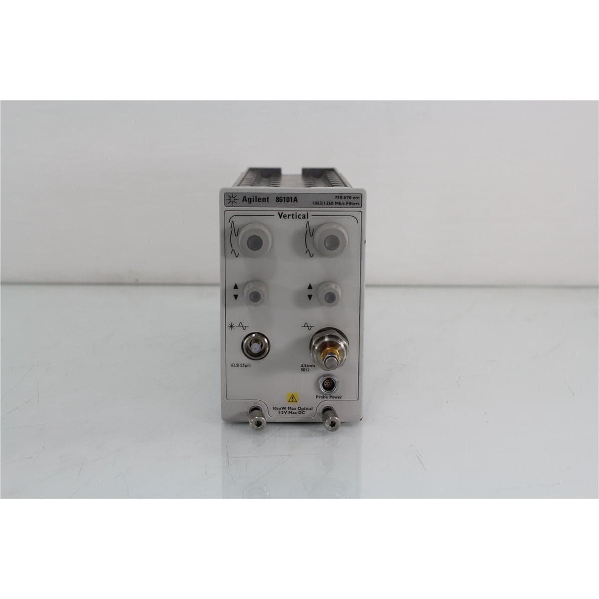
Agilent 86101A Option 202 Optical/Electrical Plug-In Module, 3 GHz Optical and 20 GHz Electrical
$3,192.00
Price in USD.
- Condition
- Used
- Availability
- In stock
- Model
- 86101A_Opt202
- Manufacturer
- Agilent
- Category
- DCA Modules
Description
Agilent 86101A Option 202 Optical/Electrical Plug-In Module, 3 GHz Optical and 20 GHz Electrical
The Agilent 86101A Option 202 is an optical/electrical plug-in module designed for compatible Agilent 86100A, 86100B, and 86100C Digital Communications Analyzer mainframes. It provides an amplified optical measurement channel and a high-speed electrical measurement channel in a single two-slot module, supporting time-domain analysis of optical and electrical communication signals.
Option 202 combines a 3 GHz optical channel with a 20 GHz electrical channel. The optical input is configured for multimode fiber signals across wavelengths from 750 nm to 860 nm, while the electrical input uses a precision 3.5 mm connector. Integrated 1063 Mb/s and 1250 Mb/s reference filters support measurements on compatible short-wavelength communication signals.
The module is useful for characterizing optical transmitters, receivers, transceivers, laser sources, communication components, and high-speed electrical interfaces. Installed in a compatible DCA mainframe, it enables waveform display, amplitude analysis, timing evaluation, eye-diagram measurements, and other signal-integrity functions supported by the host instrument.
Features and Benefits of the Agilent 86101A Option 202
The Agilent 86101A Option 202 provides a practical combination of optical and electrical measurement capability for laboratory, engineering, manufacturing, and service environments.
- Combined optical and electrical channels: Allows related optical and electrical signals to be evaluated with one plug-in module.
- 3 GHz optical bandwidth: Supports waveform analysis of compatible short-wavelength optical communication signals.
- 20 GHz electrical bandwidth: Provides high-speed electrical signal acquisition through a precision 3.5 mm input connector.
- 750 nm to 860 nm optical range: Supports compatible short-wavelength multimode fiber applications.
- Multimode optical input: Designed for 62.5/125 µm multimode optical connections with a selectable flat interface.
- Integrated reference filters: Includes 1063 Mb/s and 1250 Mb/s filter selections for supported communication measurements.
- Amplified optical receiver: Uses an internal optical-to-electrical receiver to convert incoming optical signals for waveform acquisition.
- Dual-slot module format: Installs directly in a compatible Agilent 86100-series DCA mainframe.
- Eye-diagram evaluation: Supports visualization and analysis of compatible optical and electrical digital communication waveforms.
- Laboratory and production use: Suitable for development, characterization, troubleshooting, verification, and manufacturing test workflows.
Optical Channel
The optical channel provides 3 GHz bandwidth for signals within the 750 nm to 860 nm wavelength range. This short-wavelength region is associated with compatible multimode fiber communication components, optical transmitters, laser sources, receivers, and transceiver assemblies.
An amplified optical receiver converts the incoming optical waveform into an electrical signal that can be processed by the module’s sampling circuitry and displayed by the DCA mainframe. The documented optical-to-electrical converter is part number 1GE1-4418 and has an approximate minimum conversion gain of 180 V/W.
The optical path includes switching, attenuation, filtering, conversion, and sampling circuitry. Option 202 incorporates an attenuator and two selectable internal filters as part of the optical-channel signal path.
20 GHz Electrical Channel
The electrical channel provides up to 20 GHz bandwidth through a precision 3.5 mm input connector. This channel supports analysis of compatible high-speed electrical waveforms associated with communication transmitters, receivers, clock signals, data paths, and related test fixtures.
The electrical channel can be used independently or alongside the optical channel. This combination is useful when comparing an electrical drive signal with a resulting optical output or when evaluating electrical and optical portions of a communication device within the same DCA platform.
Appropriate high-frequency cables, adapters, attenuators, and terminations should be used to preserve signal integrity. The connected signal level must remain within the safe operating range of the module and mainframe.
Integrated 1063 Mb/s and 1250 Mb/s Filters
Option 202 includes internal filters for 1063 Mb/s and 1250 Mb/s measurements. These filters allow the optical-channel response to be configured for compatible data-rate-specific testing.
Using the appropriate reference filter can help align the measurement response with the requirements of the signal or applicable test procedure. Filter selection, channel setup, wavelength, data rate, and mainframe measurement settings should be verified before recording results.
The module also supports an unfiltered optical response within its available bandwidth. The appropriate configuration depends on whether the user requires full-bandwidth waveform observation or a filtered response for a particular measurement method.
Eye-Diagram and Waveform Analysis
When installed in a compatible Agilent 86100-series Digital Communications Analyzer, the 86101A Option 202 can support eye-diagram and waveform analysis of compatible optical and electrical signals. Eye diagrams provide a visual representation of repeated digital transitions and can be used to evaluate signal quality, timing behavior, amplitude consistency, noise, and waveform distortion.
The specific measurements available depend on the installed DCA mainframe, firmware, software options, trigger configuration, and measurement setup. The module supplies the optical and electrical acquisition channels, while the mainframe provides the display, processing, controls, and analysis environment.
For consistent results, users should confirm optical wavelength, fiber type, connector compatibility, electrical input level, reference-filter selection, triggering, averaging, and calibration before performing measurements.
Typical Applications
The Agilent 86101A Option 202 Optical/Electrical Plug-In Module is suitable for professional applications such as:
- Short-wavelength optical waveform analysis
- Optical eye-diagram measurements
- High-speed electrical waveform analysis
- Multimode optical transmitter characterization
- Optical receiver and transceiver testing
- Laser source waveform evaluation
- 1063 Mb/s communication signal testing
- 1250 Mb/s communication signal testing
- Electrical-to-optical signal comparison
- Component development and verification
- Production testing and quality control
- Fiber optic system troubleshooting
Product Overview
| Brand | Agilent Technologies |
| Model | 86101A |
| Installed Option | 202 |
| Product Category | Optical/Electrical Plug-In Module |
| Optical Channel Type | Amplified optical receiver |
| Electrical Channel Type | High-speed sampling channel |
| Mainframe Compatibility | Agilent 86100A, 86100B, and 86100C Digital Communications Analyzer mainframes |
| Mainframe Space Required | Two channel slots |
| Primary Application | Time-domain analysis of optical and electrical communication signals |
Option 202 Specifications
| Specification | Details |
| Optical Bandwidth | 3 GHz |
| Electrical Bandwidth | 20 GHz |
| Optical Wavelength Range | 750 nm to 860 nm |
| Optical Fiber Input | Multimode |
| Optical Interface | 62.5/125 µm multimode, flat, user selectable |
| Electrical Connector | 3.5 mm |
| Internal Filter 1 | 1063 Mb/s |
| Internal Filter 2 | 1250 Mb/s |
| O/E Receiver Part Number | 1GE1-4418 |
| Approximate Minimum O/E Conversion Gain | 180 V/W |
Option 202 Internal Components
| Component | Details |
| Digital Board Assembly | 86101-60015 |
| Sampler Board Assembly | 83481-60027 |
| Optical Sampler Assembly | 5086-7969 |
| Electrical Sampler Assembly | 5086-7969 |
| Pulse Filter Assembly | 5086-7461 |
| Pulse Filter Driver Board | 83481-60030 |
| O/E Receiver | 1GE1-4418 |
| Attenuator | 0955-0246 |
| Filter 1 | 0955-1051 |
| Filter 2 | 0955-1052 |
| Electrical Connector Assembly | 5062-1247, 3.5 mm |
Mainframe and System Requirements
The Agilent 86101A Option 202 is a plug-in module and cannot perform measurements as a standalone instrument. It requires a compatible Agilent 86100-series Digital Communications Analyzer mainframe for power, control, acquisition, display, calibration, and waveform analysis.
The module occupies two channel slots in the host instrument. Buyers should confirm that the intended DCA mainframe has sufficient available space and supports the module through its installed firmware and hardware configuration.
Measurement accessories may include compatible optical adapters, multimode patch cords, high-frequency electrical cables, attenuators, adapters, triggering equipment, and calibration devices. Only accessories specifically listed with the individual unit should be considered included.
Optical Input and Connector Care
The optical input should be used with compatible multimode fiber and the appropriate user-selectable optical adapter. The installed adapter should be inspected to confirm fiber type, connector family, ferrule polish, and physical condition before connecting a test cable.
Optical connector end faces should be inspected and cleaned before every connection. Dust, residue, scratches, or damaged ferrules can increase loss, reduce optical return loss, introduce instability, and contaminate the module’s internal optical interface.
Patch cords should be routed with suitable bend-radius control and strain relief. Excessive bending, pulling, or lateral force at the optical input can affect transmitted power and damage the patch cord or module interface.
Calibration and Warm-Up
The module should be installed in the mainframe and allowed to warm up for at least one hour before calibration or precision performance verification. A user module calibration should be completed before optical and electrical performance tests and before optical-to-electrical calibration.
The module should not be removed or installed while calibration is in progress. Interrupting calibration can cause loss of calibration data or improper operation of the host instrument.
Calibration status can affect vertical accuracy, optical responsivity, electrical-channel performance, and waveform measurements. Users should follow the applicable mainframe and plug-in module procedures before recording critical test results.
Comprehensive Functional and Performance Testing
When calibration is technically applicable and supported, the Agilent 86101A Option 202 is calibrated before shipment. The calibration process may include user module calibration, extended vertical channel calibration, optical-to-electrical calibration, optical responsivity checks, electrical-channel verification, and filter-path evaluation.
Following successful calibration, the module may include a calibration label, calibration certificate, and related measurement data, depending on the selected service and equipment condition.
If formal calibration is unavailable or not applicable, the module receives comprehensive functional and performance testing. Testing may include mainframe recognition, optical-channel response, electrical-channel response, attenuation-path operation, 1063 Mb/s and 1250 Mb/s filter selection, optical input inspection, electrical connector inspection, and basic waveform acquisition.
The exact calibration scope, compatible mainframe, measurement accessories, supplied test data, documentation, and service records should be confirmed before purchase when these items are required for laboratory, manufacturing, regulatory, or quality-management applications.
Buyer Considerations
The Agilent 86101A Option 202 is a configuration-specific optical/electrical sampling module. Buyers should confirm that the 3 GHz optical bandwidth, 20 GHz electrical bandwidth, 750 nm to 860 nm wavelength range, multimode optical input, 3.5 mm electrical connector, and installed filters match the intended test application.
The 86101A Option 202 should not be confused with other 86101A options or with longer-wavelength optical modules. Different options may provide different wavelength ranges, fiber types, bandwidths, filters, attenuators, or connector arrangements.
Buyers should review the physical condition, optical adapter, electrical connector, filter operation, mainframe recognition, calibration status, service history, and included accessories. The DCA mainframe, optical patch cords, electrical cables, adapters, calibration equipment, and test fixtures may be required separately.
Why Buy from AssetRelay?
AssetRelay supplies professional equipment and product solutions for fiber optic, telecom, laboratory, production, inspection, cleaning, RF/microwave, electronic test, and photonics applications. The Agilent 86101A Option 202 helps engineers, laboratories, production facilities, procurement teams, and service organizations perform short-wavelength optical and high-speed electrical waveform measurements with compatible DCA mainframes.
Buyers should review the available product photographs, physical condition, optical input, electrical connector, installed options, included accessories, calibration information, and mainframe compatibility before purchase.
Only accessories and system components specifically identified in the product listing should be considered included. The Agilent 86100-series mainframe, optical adapters, multimode patch cords, 3.5 mm electrical cables, attenuators, calibration equipment, and related test fixtures may be required separately.