
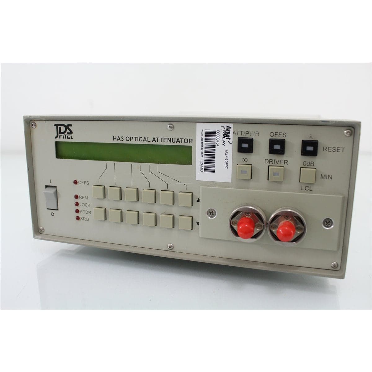
JDS · HA37-10FP7
JDS FITEL HA37+10FP7 High-Resolution Single-Mode Variable Optical Attenuator
$4,379.20
Price in USD.
- Condition
- Used
- Availability
- In stock · 3 available
- Model
- HA37-10FP7
- Manufacturer
- JDS
- Category
- Optical Attenuators 9-125
Description
JDS FITEL HA37+10FP7 High-Resolution Single-Mode Variable Optical Attenuator
The JDS FITEL HA37+10FP7 is a precision variable optical attenuator designed for controlled signal-level adjustment in single-mode fiber optic test systems. Based on the JDS FITEL HA3 Series platform, the instrument combines fine attenuation resolution, excellent repeatability, low insertion loss, low polarization dependence, and a high-isolation optical beam block.
The attenuator operates across wavelengths from 1200 nm to 1700 nm and provides a wavelength-dependent attenuation range of at least 60 dB. Its 0.0005 dB nominal resolution supports applications requiring exceptionally small and repeatable optical-level changes.
The HA3 platform uses Siecor 9/125 µm single-mode fiber and handles optical input power up to 200 mW. It is suitable for receiver sensitivity testing, optical component characterization, system loss simulation, source-level control, optical power meter testing, calibration, and automated production measurements.
The complete HA37+10FP7 designation should be retained from the instrument label because it identifies a specific factory configuration. The installed connector type, port arrangement, optional coupler or switch, and other configuration details should be confirmed directly from the individual unit.
Features and Benefits of the JDS FITEL HA37+10FP7
- High-resolution attenuation control: Provides 0.0005 dB nominal setting resolution for exceptionally fine optical-level adjustment.
- Wide wavelength coverage: Supports compatible single-mode signals from 1200 nm to 1700 nm.
- At least 60 dB attenuation: Provides broad signal-level control across the documented wavelength range.
- Excellent repeatability: Offers ±0.006 dB repeatability at constant temperature, wavelength, and polarization state.
- Accurate attenuation settings: Provides ±0.1 dB accuracy when the calibration wavelength or user slope is optimized.
- Low insertion loss: Introduces less than 2.0 dB of internal optical loss, excluding connectors and optional optical devices.
- Low polarization-dependent loss: Provides 0.02 dB typical and 0.08 dB maximum PDL under the documented conditions.
- High return loss: Provides greater than 60 dB internal return loss under the specified measurement conditions.
- Fast attenuation changes: Changes from 0 dB to 60 dB in 2.5 seconds or less.
- High-isolation beam block: Provides more than 110 dB of optical isolation.
- Fast beam-block response: Interrupts the optical path in less than 20 milliseconds.
- High optical input capability: Accepts optical power up to 200 mW.
- Universal AC input: Operates from 90 V to 240 V AC at 50 Hz to 60 Hz.
- Rack-mount compatibility: Uses a compact half-rack enclosure compatible with 19-inch rack installation.
High-Resolution Optical Attenuation
The HA3 Series provides 0.0005 dB nominal attenuation resolution. This fine resolution supports optical measurements in which very small changes in signal level must be applied repeatedly and accurately.
High-resolution attenuation is useful for characterizing receiver thresholds, evaluating optical detector response, measuring small changes in component transmission, and testing the linearity of optical power meters.
The setting resolution should not be interpreted as total measurement uncertainty. Actual optical power at the output also depends on attenuation accuracy, source stability, wavelength, connector condition, polarization, external fiber loss, and the measurement reference plane.
1200 nm to 1700 nm Wavelength Range
The JDS FITEL HA37+10FP7 operates across wavelengths from 1200 nm to 1700 nm. This broad range covers common single-mode telecommunications and photonics applications near 1310 nm, 1490 nm, 1550 nm, and 1625 nm.
The source, patch cords, connector interfaces, optical sensors, receivers, and devices under test should also support the selected wavelength.
Attenuation range and accuracy vary with wavelength. Precision measurements should use the appropriate wavelength setting, calibration wavelength, or user-defined slope correction for the optical source being used.
Attenuation Range
The HA3 platform provides a wavelength-dependent attenuation range of at least 60 dB. This wide range supports both small optical-level adjustments and substantial signal reduction.
Low attenuation settings are useful for fine component measurements, while higher settings support receiver sensitivity testing, weak-signal simulation, detector characterization, and optical loss-budget evaluation.
The instrument changes from 0 dB to 60 dB in 2.5 seconds or less, supporting automated level sweeps and production procedures requiring several attenuation points.
Attenuation Accuracy and Repeatability
Attenuation accuracy is specified at ±0.1 dB when the calibration wavelength or user slope is optimized. If optimization is not performed, accuracy from 1260 nm to 1360 nm and from 1450 nm to 1570 nm is the greater of ±0.1 dB or ±0.004 dB per decibel of attenuation.
At other wavelengths, the unoptimized accuracy is the greater of ±0.1 dB or ±0.015 dB per decibel of attenuation.
Attenuation repeatability is specified at ±0.006 dB under constant temperature, wavelength, and polarization conditions. This supports test sequences that repeatedly return to the same optical-level settings.
Low Insertion Loss
Internal insertion loss is less than 2.0 dB under the documented measurement conditions. This value excludes losses from external connectors and any optional switch or coupler installed in the optical path.
Low insertion loss helps preserve available source power and measurement dynamic range, particularly in systems containing several patch cords, adapters, switches, couplers, and other optical components.
The total loss through the complete test path should be established with a calibrated optical power meter when precise output levels are required.
Low Polarization-Dependent Loss
Polarization-dependent loss is documented at 0.02 dB typical and 0.08 dB maximum. These values apply at 23 °C with a laser source under the specified test conditions.
Low PDL helps reduce changes in attenuation caused by variations in the input signal’s state of polarization. This is useful when testing receivers, passive components, amplifiers, and transmission systems where uncontrolled polarization changes could affect the measured optical level.
The complete optical setup can still introduce polarization-related variation through external patch cords, connectors, switches, couplers, and the device under test.
High Return Loss
Internal return loss is specified at greater than 60 dB under the documented conditions. This value represents the total contribution of discrete internal reflections and does not include distributed reflection in the optical fiber.
High return loss helps reduce reflected optical power that could destabilize a laser source or affect the performance of a sensitive optical system.
External connector polish, adapter condition, patch-cord quality, and connector cleanliness also influence the return loss of the complete measurement path.
High-Isolation Beam Block
The HA3 Series includes an optical beam block providing more than 110 dB of attenuation. The beam block can interrupt the optical path without requiring the source to be switched off or the programmed attenuation setting to be changed.
Beam-block response is less than 20 milliseconds. This fast switching supports dark measurements, receiver protection, automated test sequences, and transitions between signal-on and signal-off conditions.
The beam block should not replace established laser-safety procedures. Optical sources should still be disabled before connectors are inspected, cleaned, installed, or removed.
Optional Optical Configurations
The HA1 and HA3 Series were available with optional internal optical devices. Available configurations included no additional optical device, a 50/50 coupler, a 10/90 coupler, a 2/98 coupler, or a 1x2 optical switch.
The trunk fiber of the optional device connects internally to the attenuator. An installed coupler provides additional optical ports, while the optional 1x2 switch supports selection between compatible optical paths.
These options should only be included in the final product configuration when the corresponding ports or model information are verified on the individual HA37+10FP7.
Typical Applications
- Single-mode optical receiver sensitivity testing
- Controlled optical loss simulation
- Fiber optic component characterization
- Optical power meter linearity testing
- Optical detector evaluation
- Transceiver testing
- Insertion loss and transmission measurements
- Optical amplifier test systems
- Wavelength-dependent component testing
- Automated optical-level sweeps
- Laboratory instrument calibration
- Production screening and quality assurance
Product Overview
| Brand | JDS FITEL |
| Model | HA37+10FP7 |
| Product Series | HA3 Series |
| Product Category | High-Resolution Variable Optical Attenuator |
| Fiber Type | Siecor 9/125 µm single-mode fiber |
| Wavelength Range | 1200 nm to 1700 nm |
| Attenuation Range | At least 60 dB, wavelength dependent |
| Nominal Resolution | 0.0005 dB |
| Beam Block | Greater than 110 dB isolation |
| Primary Application | Precision single-mode optical signal-level control and loss simulation |
Optical Specifications
| Specification | Details |
| Wavelength Range | 1200 nm to 1700 nm |
| Attenuation Range | At least 60 dB, continuous and wavelength dependent |
| Nominal Attenuation Resolution | 0.0005 dB |
| Attenuation Repeatability | ±0.006 dB |
| Attenuation Change Rate | 2.5 seconds or less from 0 dB to 60 dB |
| Optimized Attenuation Accuracy | ±0.1 dB |
| Insertion Loss | Less than 2.0 dB |
| Return Loss | Greater than 60 dB |
| Typical Polarization-Dependent Loss | 0.02 dB |
| Maximum Polarization-Dependent Loss | 0.08 dB |
| Maximum Optical Input Power | 200 mW |
| Beam Block Attenuation | Greater than 110 dB |
| Beam Block Speed | Less than 20 ms |
| Recommended Recalibration Interval | One year |
Unoptimized Accuracy Specifications
| Wavelength Region | Accuracy without Calibration-Wavelength or User-Slope Optimization |
| 1260 nm to 1360 nm | The greater of ±0.1 dB or ±0.004 dB per dB |
| 1450 nm to 1570 nm | The greater of ±0.1 dB or ±0.004 dB per dB |
| Other Wavelengths within 1200 nm to 1700 nm | The greater of ±0.1 dB or ±0.015 dB per dB |
Electrical, Physical and Environmental Specifications
| Specification | Details |
| AC Input | 90 V to 240 V AC |
| Line Frequency | 50 Hz to 60 Hz |
| Maximum Power Consumption | 80 VA |
| Dimensions | 21.2 x 8.9 x 35.5 cm, W x H x D |
| Rack Format | 2U high and one-half rack width |
| Rack Compatibility | Compatible with the HP 8156A mechanical format |
| Weight | 4 kg |
| Operating Temperature | 0 °C to 40 °C |
| Storage Temperature | -40 °C to 60 °C |
| Humidity | 95% relative humidity up to 40 °C, decreasing by 5% per °C from 40 °C to 60 °C |
Available Optical Options
| Option | Configuration |
| None | Standard attenuator configuration without an additional internal optical device |
| 50/50 Coupler | Internal coupler with equal nominal output division |
| 10/90 Coupler | Internal coupler with nominal 10% and 90% output division |
| 2/98 Coupler | Internal coupler with nominal 2% and 98% output division |
| 1x2 Switch | Internal optical switch for selection between compatible optical paths |
Available Port and Connector Configurations
| Configuration | Available Options |
| Port Type | Pigtails with or without connectors, or panel-mounted connectors |
| Connector Type | FC/PC, FC/APC, SC/PC, SC/APC, or no connector |
Configuration Details Requiring Verification
| Configuration Item | Verification Required |
| Port Type | Confirm pigtail or panel-mounted optical interfaces |
| Connector Type | Confirm FC/PC, FC/APC, SC/PC, SC/APC, or another installed configuration |
| Internal Optical Option | Confirm whether a coupler or 1x2 switch is installed |
| Remote Interface | Confirm the available communication ports and command support on the individual unit |
Installation and Measurement Setup
The HA37+10FP7 should be installed on a stable laboratory bench or in an appropriate 19-inch rack using compatible mounting hardware. Adequate clearance should be maintained for ventilation, optical cables, communication cables, and AC power.
The optical port type and connector polish should be confirmed before patch cords are attached. All optical connectors should be inspected and cleaned before mating.
When connecting a sensitive receiver or detector, the attenuator should initially be set to a high attenuation value. Attenuation can then be reduced gradually while the optical output and device response are monitored.
The optical input must remain below the documented 200 mW limit. A calibrated optical power meter should be used when the exact output power at the device under test must be recorded.
Comprehensive Functional and Performance Testing
The JDS FITEL HA37+10FP7 receives comprehensive functional and performance testing before shipment. Evaluation may include AC power operation, startup, display response, front-panel controls, attenuation adjustment, beam-block operation, and available remote-control functions.
Optical testing may include input-to-output continuity, insertion loss, representative attenuation settings, attenuation repeatability, attenuation range, response time, polarization-dependent loss, return loss, and beam-block isolation using suitable calibrated equipment.
The optical interfaces, pigtails or bulkheads, connectors, front-panel controls, display, communication ports, AC inlet, enclosure, model label, and installed options may be inspected for contamination, damage, corrosion, or excessive wear.
The exact testing scope depends on the verified port type, connector configuration, internal optical options, available single-mode sources, reference patch cords, optical power meters, return-loss equipment, and requested wavelength and attenuation points.
Calibration Before Shipment
When technically applicable and selected, the JDS FITEL HA37+10FP7 can be calibrated or performance-verified before shipment. Evaluation may include insertion loss, attenuation accuracy, attenuation repeatability, wavelength response, polarization-dependent loss, return loss, beam-block isolation, and switching speed.
Calibration documentation should identify the attenuator model and serial number, fiber configuration, optical connectors, test wavelength, attenuation settings, input power, reference patch cords, measurement equipment, recorded results, environmental conditions, and applicable measurement uncertainty.
Buyers requiring formal calibration should specify the required wavelengths, attenuation points, connector configuration, optical input level, return-loss measurements, certificate format, recorded data, and required measurement uncertainty before purchase.
Why Buy from AssetRelay?
AssetRelay supplies professional equipment and product solutions for fiber optic, telecommunications, optical testing, photonics, laboratory, production, inspection, electronic testing, RF/microwave, and technical research applications. The JDS FITEL HA37+10FP7 provides high-resolution optical attenuation for receiver developers, component manufacturers, telecommunications laboratories, production facilities, system integrators, universities, and research organizations.
Buyers should review the exact model label, single-mode fiber configuration, port type, connector polish, attenuation range, insertion loss, beam-block operation, installed optical options, remote interfaces, functional test results, calibration status, and included accessories before purchase.